
Sewing machine with automatic threading mechanism

a technology of automatic threading and sewing machine, which is applied in the field of sewing machines, can solve the problems of increased size and installation complexity of the thread hooking device, increased cost, and increased installation space, and achieve the effect of reliable hooking

Inactive Publication Date: 2006-01-19
BROTHER KOGYO KK
View PDF9 Cites 5 Cited by
  • Summary
  • Abstract
  • Description
  • Claims
  • Application Information

AI Technical Summary

Benefits of technology

[0008] Therefore, an object of the present invention is to provide a sewing machine with a simplified thread guide thread hook mechanism which hooks the thread onto the needle bar thread guide, requiring less installation space.
[0010] Because the above configured sewing machine is provided with the needle bar to support the sewing needle, the thread take-up lever, the needle thread supply, the thread tension regulator, a plurality of the thread hooking sections including the thread take-up and the thread tension regulator, the threading mechanism to automatically pass the needle thread through the eye of the sewing needle, the thread transferring mechanism, the needle bar thread guide and a thread guide thread hook mechanism, when the thread transferring member of the thread transferring mechanism is moved to the vicinity of the eye of the sewing needle, the thread hookmember is moved nearly parallel to the vertical surface. Therefore the needle thread can be reliably hooked on the needle bar thread guide in the lower end of the needle bar by hooking the needle thread placed in between the thread transferring member and the thread take-up lever by moving the thread hook member.

Problems solved by technology

Because the threading device described in the above patent is configured with numerous members such as the base member, movable member, rotatable arm and the hook member, the thread hooking device suffers from increased size and installation complexity.
Furthermore because the hook member in the thread hooking device not only rotates horizontally but slides as well, large space is required in the lower end of the needle bar, which is another problem.
Yet furthermore, in case the thread hooking device is applied to a sewing machine that does not use a thread cassette, a separate drive source to horizontally rotate and slide the hook member is required, which demands even larger installing space and increased cost.

Method used


Image

  • Sewing machine with automatic threading mechanism
  • Sewing machine with automatic threading mechanism
  • Sewing machine with automatic threading mechanism

Examples


Embodiment Construction

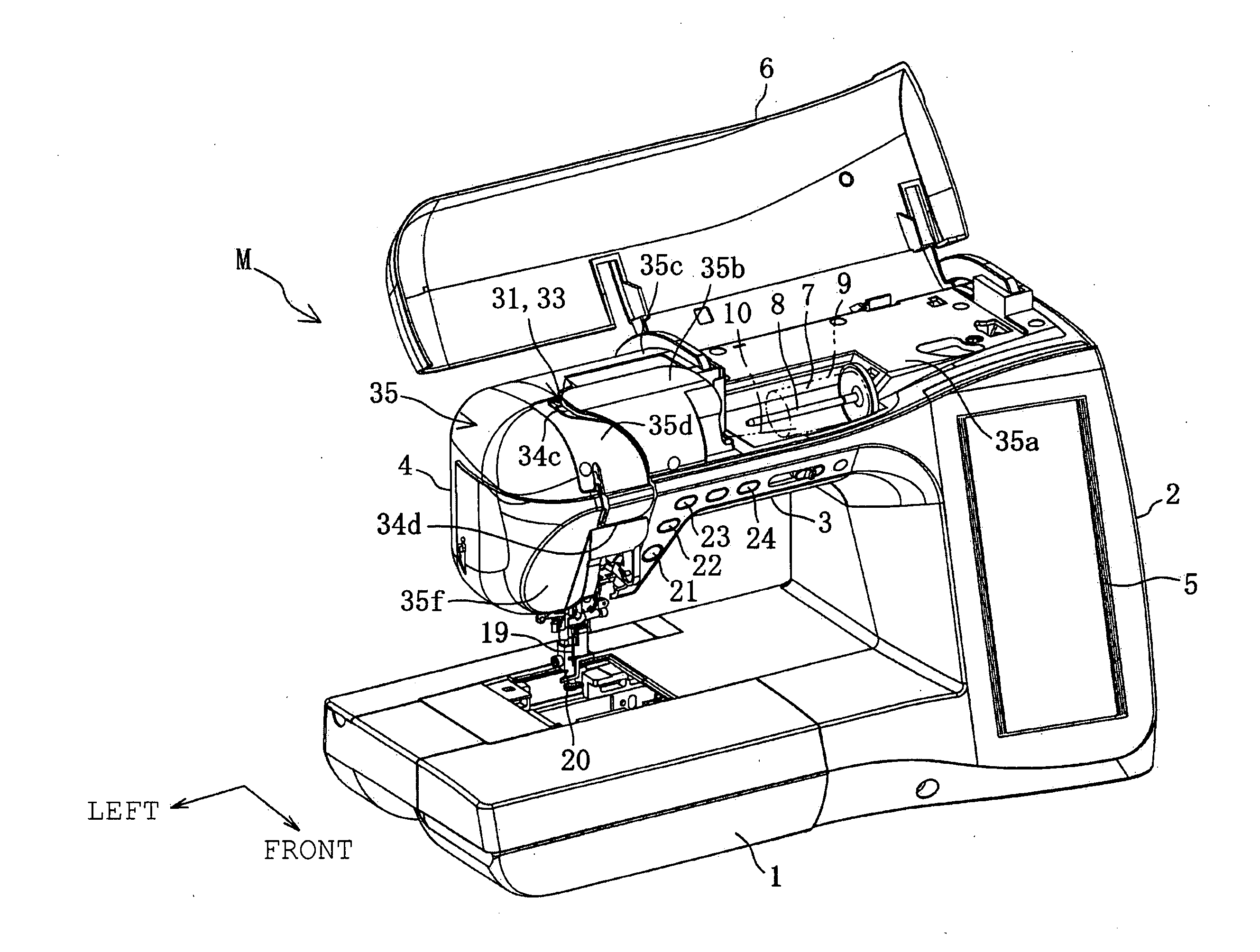
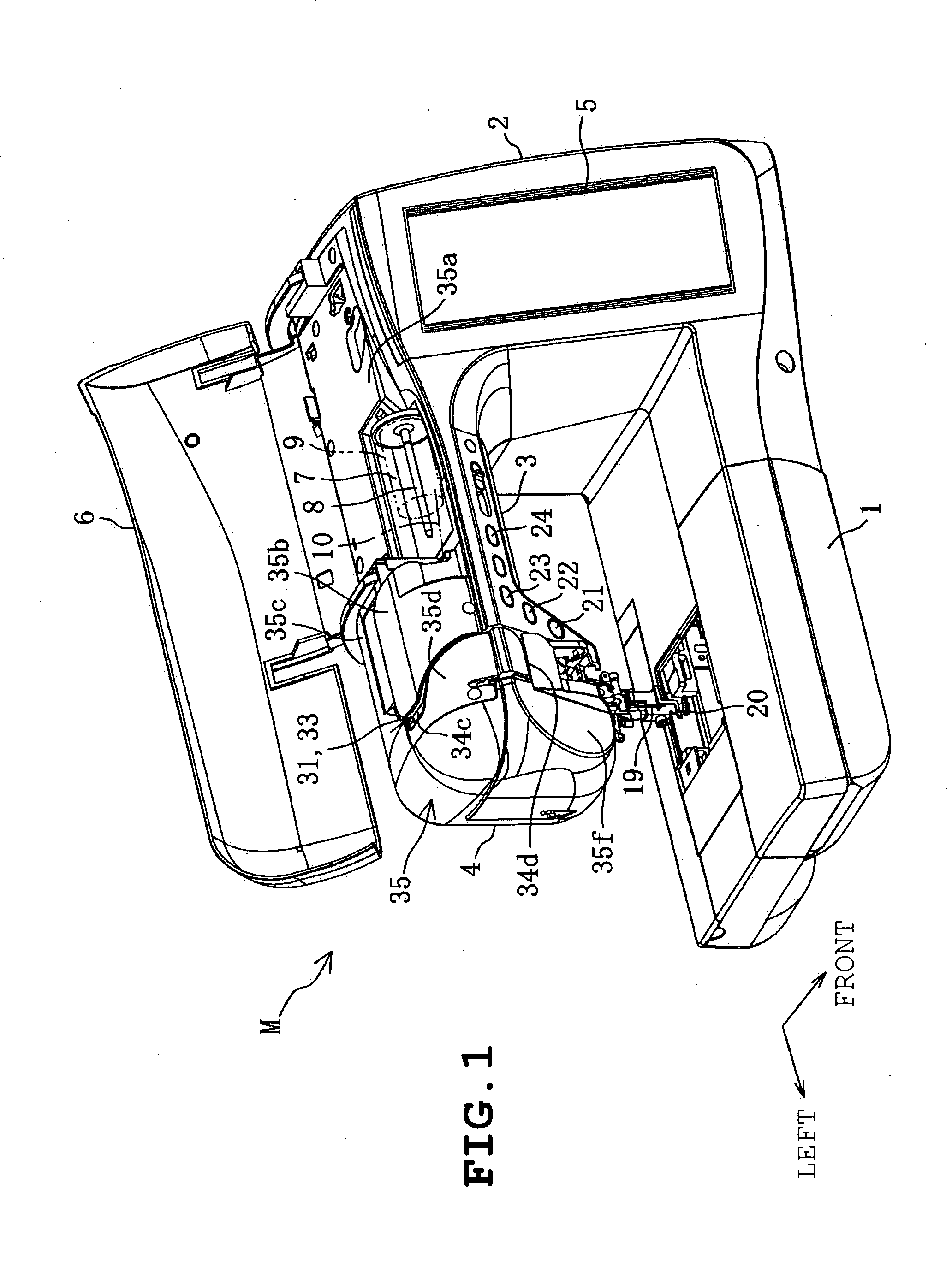
[0045] As shown in FIGS. 1 to 3, the sewing machine M is provided with a bed 1, a foot pillar 2 standing on the right side portion of the bed 1, an arm 3 extending to the left from the upper portion of the foot pillar 2 to converge with the bed 1 and a head 4 arranged on the left portion of the arm 3. A needle plate (not shown) below which a rotary hook mechanism (not shown) is placed is arranged on the bed 1. A bobbin wrapped with the lower thread is detachably attached to the rotary hook mechanism. In front of the foot pillar a large type vertical liquid crystal display 5 is arranged.

[0046] In the arm 3, an openable cover 6 is mounted. This openable cover is arranged laterally across the entire length of the arm 3 and is pivotally supported about the laterally directed axis in the upper-rear end of the arm 3 in an openable manner. In the right side of the head 4, a thread accommodating concave 7 is formed on top of the arm 3 and a spool pin 8 is arranged in the thread accommodati...


PUM


Abstract

A sewing machine includes a plurality of thread hooking sections including a thread take-up lever and a thread tension regulator, and a thread guide thread hook mechanism having a thread hook member which is moveable nearly parallel to the vertical surface from a stand-by position to a thread hooking position. The sewing machine is configured to hook the extent of the needle thread from a thread transferring member moved to the vicinity of the eye to the thread take-up lever to hook it onto the needle bar thread guide.

Description

BACKGROUND OF THE INVENTION [0001] 1. Field of the Invention [0002] The present invention relates to a sewing machine that transfers the needle thread drawn from a thread supply with a thread transferring mechanism to hook the needle thread onto a plurality of thread hook sections such as needle bar thread guide etc. with an automatic thread hooking device. [0003] 2. Description of the Related Art [0004] In a conventional sewing machine, the needle thread drawn from a thread spool is hooked onto a plurality of thread hooking sections (thread tension regulator, check spring and thread take-up, needle bar thread guide etc.) in a predetermined sequence and path and ultimately transferred to the sewing needle attached to the needle bar. The needle thread is then automatically passed through an eye of a sewing needle and sewing can be started. In case the sewing machine is provided with a threading mechanism, automatic threading is performed to pass the thread through the eye. [0005] Var...

Claims


Application Information

Patent Timeline
IPC IPC(8): D05B53/00
CPCD05B49/00D05B87/02D05B55/00
Inventor SHOJI, YOSHIHISAFUJIHARA, SHINYAMIZUNO, NOBORU
Owner BROTHER KOGYO KK
Learn More