
Rotary die cutter for forming a non-linear line of perforations in a strip of material

a technology of nonlinear perforations and die cutters, which is applied in the direction of metal working apparatus, stock shearing machines, manufacturing tools, etc., can solve the problems of high cost of tooling required to make such a line of perforations, the design may not be the most advantageous configuration for the article or package, and the difficulty of seeing the obj

Inactive Publication Date: 2006-01-19
WAGNER KENNETH JOHN +1
View PDF53 Cites 42 Cited by
  • Summary
  • Abstract
  • Description
  • Claims
  • Application Information

AI Technical Summary

Benefits of technology

"This patent is about a machine that makes non-linear lines of small holes in a material. It has two rolls, one with a hard surface and one with a knife that makes the holes. The material passes through the rolls and gets cut by the knife, making a non-linear line of holes. The machine is designed to make these holes quickly and accurately."

Problems solved by technology

However, one drawback with using a linear line of perforations is that such a design may not be the most advantageous configuration for the article or package it is to be used in or on.
Another problem with refastenable, disposable pant-like garments is that the attachment members tend to cover up a major portion of the lines of perforations and makes them hard to be seen.
Up until now, manufacturers have shied away from having to create a non-linear line of perforations in their products and / or packages because the cost of the tooling required to make such a line of perforations is expensive and the engineering needed to make the tooling work at high speeds is difficult.

Method used


Image

  • Rotary die cutter for forming a non-linear line of perforations in a strip of material
  • Rotary die cutter for forming a non-linear line of perforations in a strip of material
  • Rotary die cutter for forming a non-linear line of perforations in a strip of material

Examples


Embodiment Construction

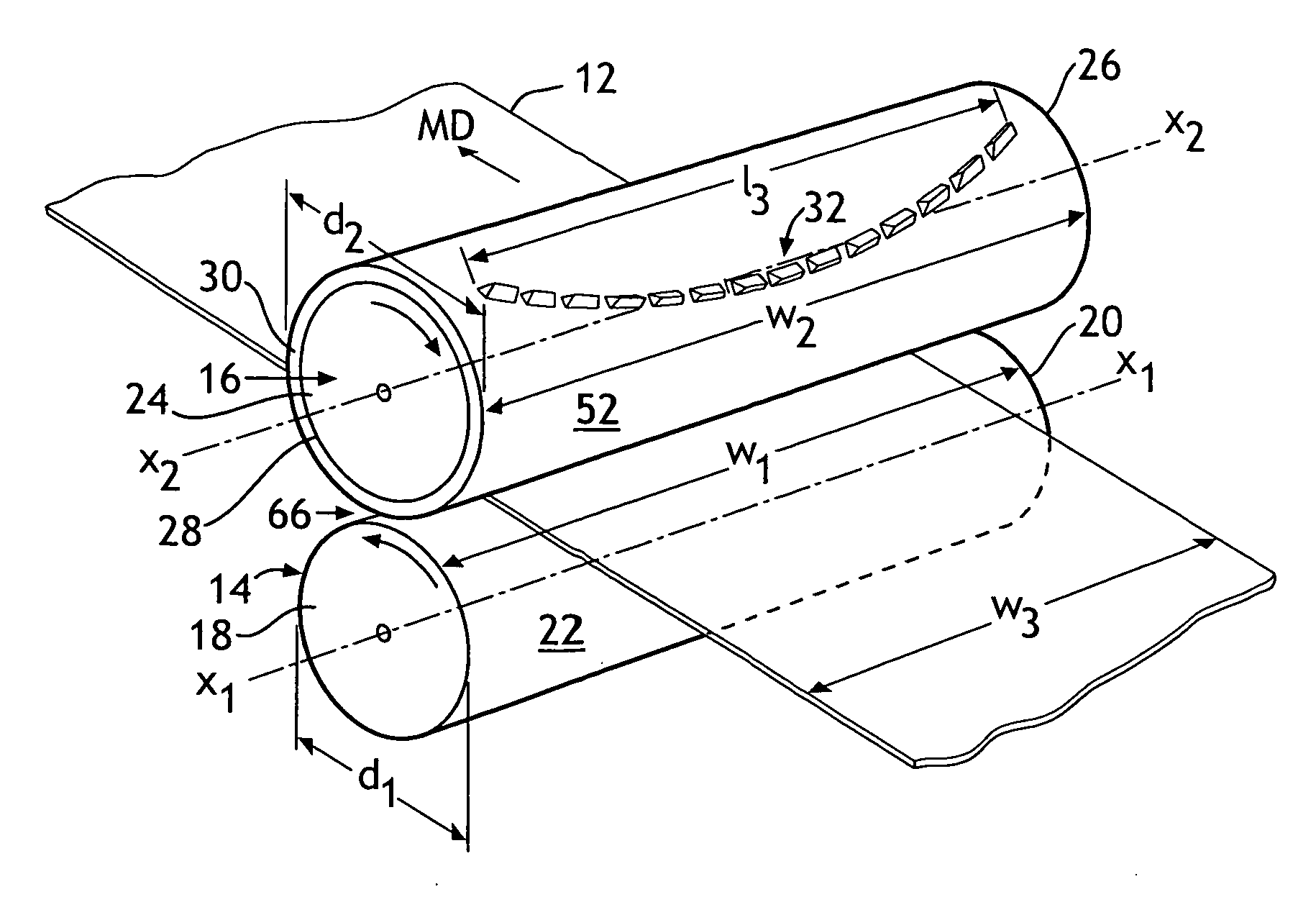
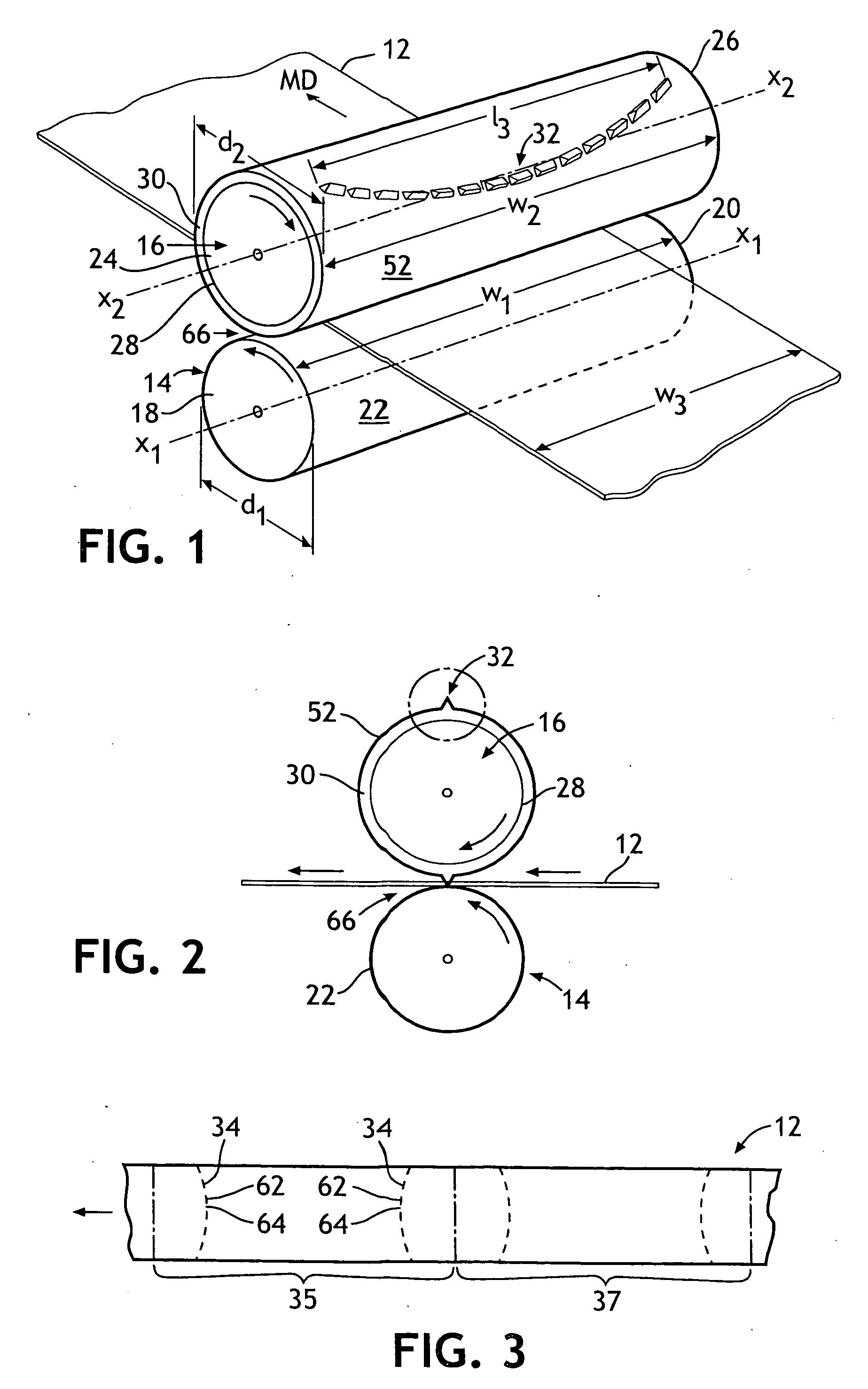
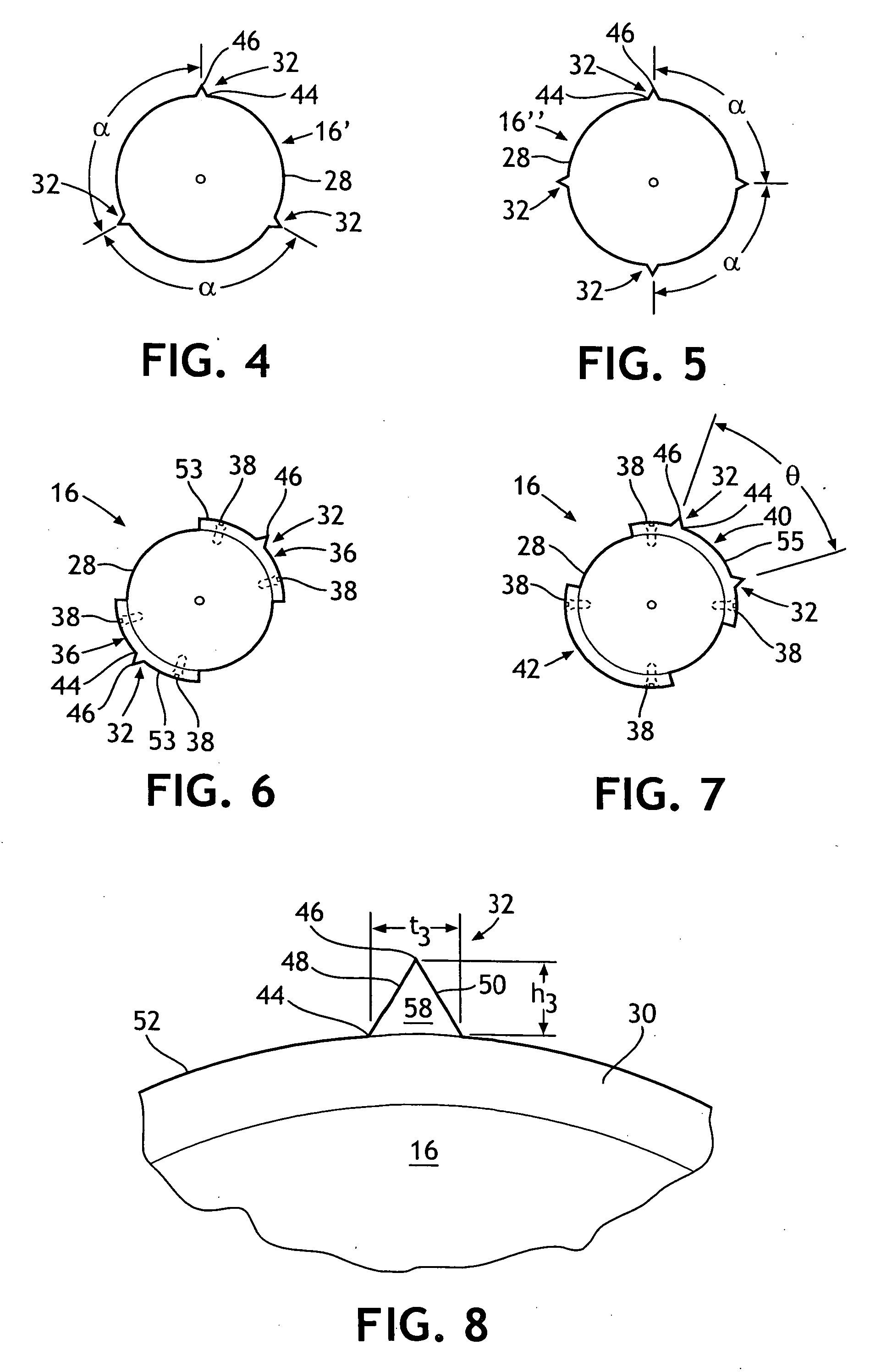
[0018] Referring to FIGS. 1 and 2, a rotary die cutter 10 is shown for forming at least one non-linear line of perforations in a strip of material 12. The rotary die cutter 10 includes a rotatable anvil roll 14 and a rotatable knife roll 16. The anvil roll 14 is cylindrical in shape and has a first end 18, a second end 20 spaced apart from said first end 18, and a longitudinal central axis X1-X1. The anvil roll 14 can be a solid roll that has a hardened peripheral surface 22 located between the first and second ends, 18 and 20 respectively. The anvil roll 14 can be formed from ferrous metal, steel, a steel alloy or from some other material known to those skilled in the art. Desirably, the peripheral surface 22 is smooth and free from irregularities, roughness or projections. Most desirably, the peripheral surface 22 has an even consistency of smoothness throughout. The anvil roll 14 has a diameter d1 that can be of almost any desired dimension. The exact diameter d1 of the anvil rol...


PUM

PropertyMeasurementUnit
face width w2aaaaaaaaaa
diameter d1aaaaaaaaaa

Abstract

A rotary die cutter for forming a non-linear line of perforations in a strip of material is disclosed. The rotary die cutter includes a rotatable anvil roll and a rotatable knife roll. The knife roll has a peripheral surface with at least one knife formed thereon. The knife has a non-linear configuration. The knife extends across at least about half of the width of the knife roll and has a plurality of land areas each separated by a notch. The knife roll is coaxially aligned with the anvil roll to form a nip therebetween through which the strip of material can pass. For each rotation of the die cutter, the knife will pass through the strip of material and be brought into direct contact with the anvil roll and form a non-linear line of perforations in the strip of material.

Description

[0001] This application is a divisional of application Ser. No. 10 / 394,360 entitled “A ROTARY DIE CUTTER FOR FORMING A NON-LINEAR LINE OF PERFORATIONS IN A STRIP OF MATERIAL” and filed in the U.S. Patent and Trademark Office on Mar. 21, 2003, the entirety of which is hereby incorporated by reference.BACKGROUND OF THE INVENTION [0002] Today, there exist many articles and packages that include a strip of material that has at least one tearable line of perforations formed therein. The tearable line of perforations can be torn open so as to open the article or to open the package in which the article is contained. Various packaging materials use a tear strip or a tearable line of perforations to enable the end user to easily open the package. Some disposable absorbent articles, such as infant diapers, child training pants, adult incontinence pants, feminine menstrual pants, etc. employ one or two lines of perforations to allow the wearer to open, inspect and even change the product with...

Claims


Application Information

Patent Timeline
Patent Type & Authority Applications(United States)
IPC IPC(8): B26D1/56B26D7/20B26F1/20
CPCB26D7/20B26F1/20B26D2007/202Y10T83/483Y10T83/9408
Inventor WAGNER, KENNETH JOHNMLINAR, JOSEPH ANDREW
Owner WAGNER KENNETH JOHN
Learn More