
Method and apparatus for predicting failure in a system

Inactive Publication Date: 2006-01-12
VEXTEC CORP
View PDF12 Cites 27 Cited by
  • Summary
  • Abstract
  • Description
  • Claims
  • Application Information

AI Technical Summary

Benefits of technology

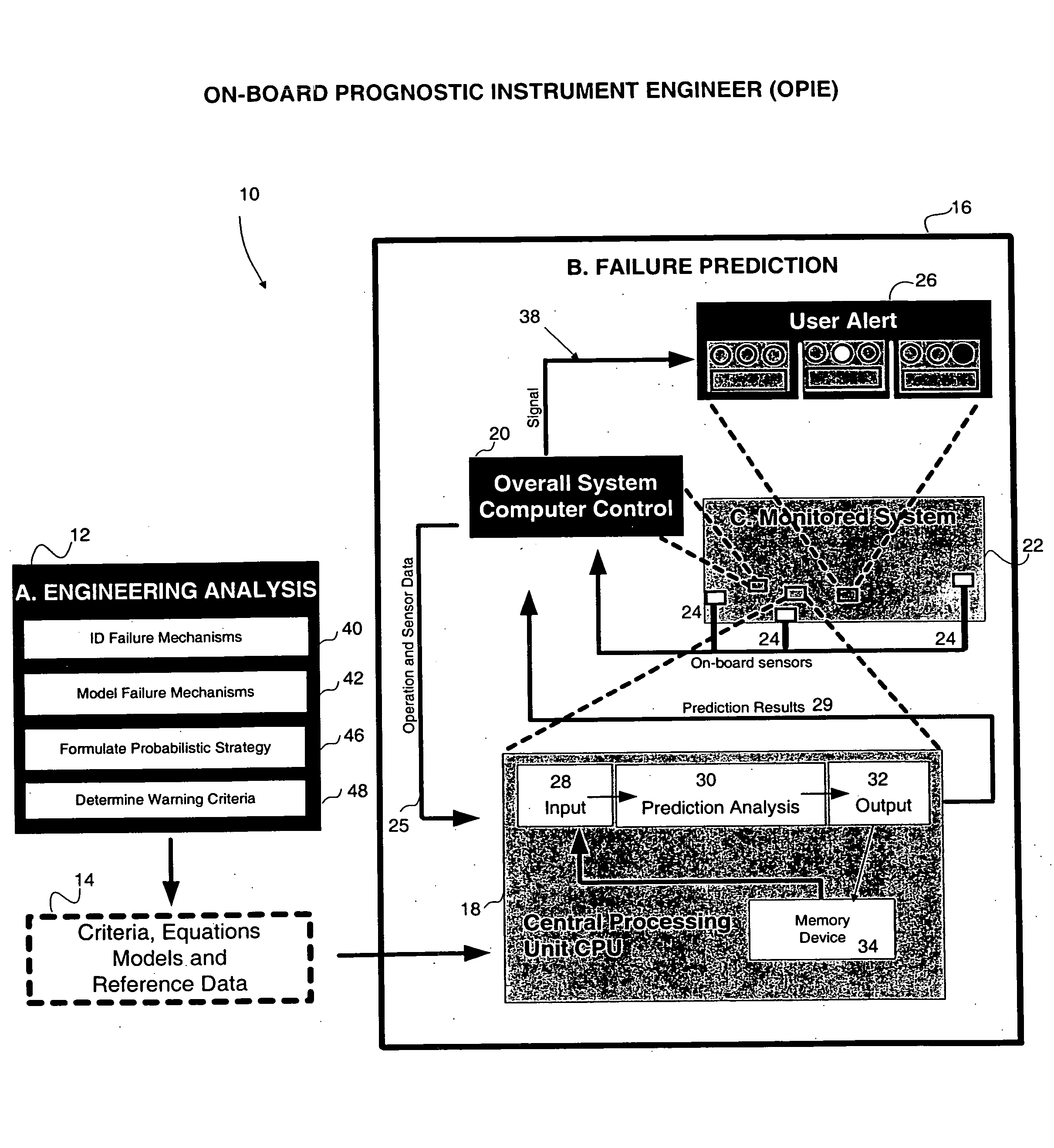
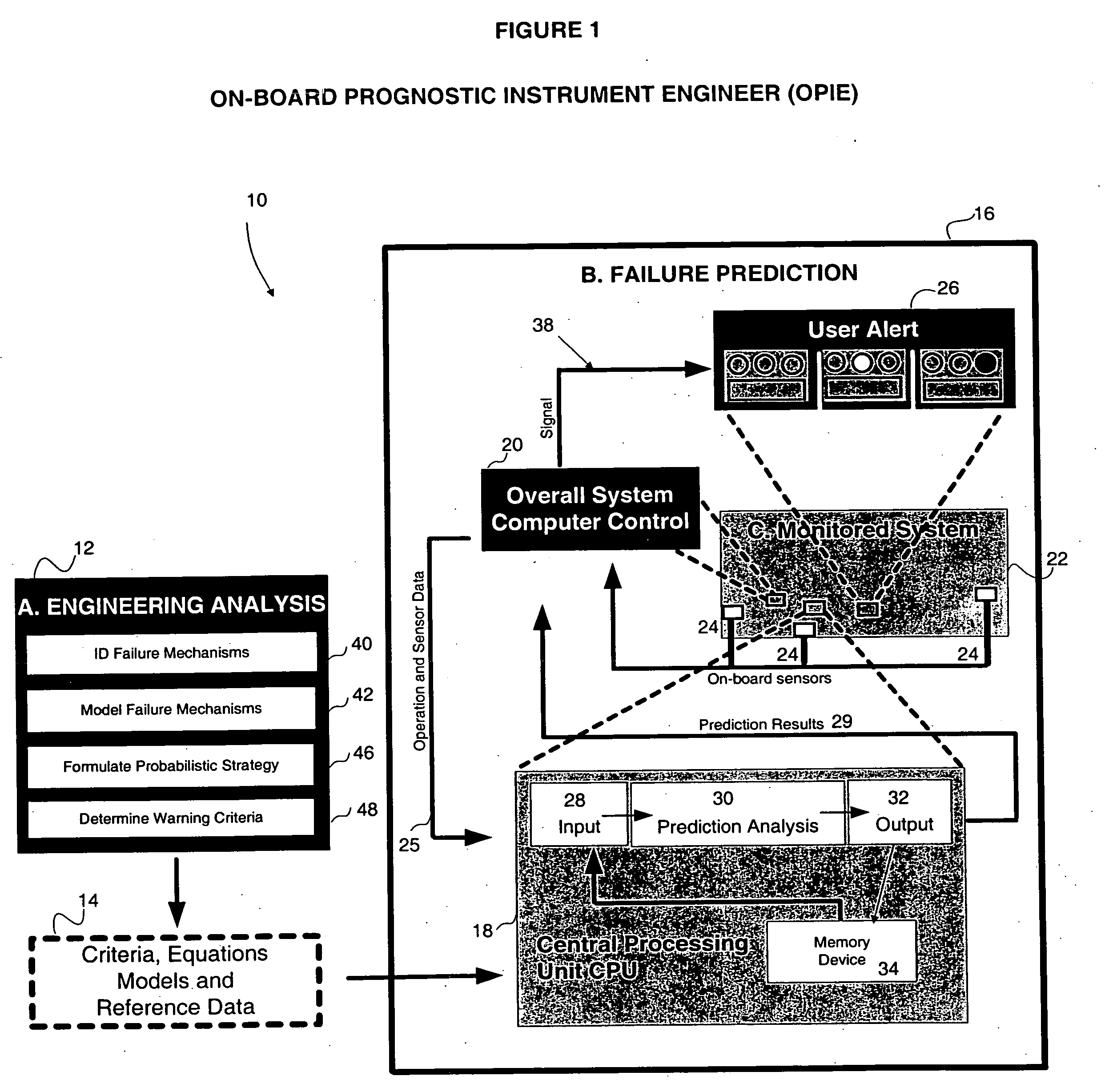
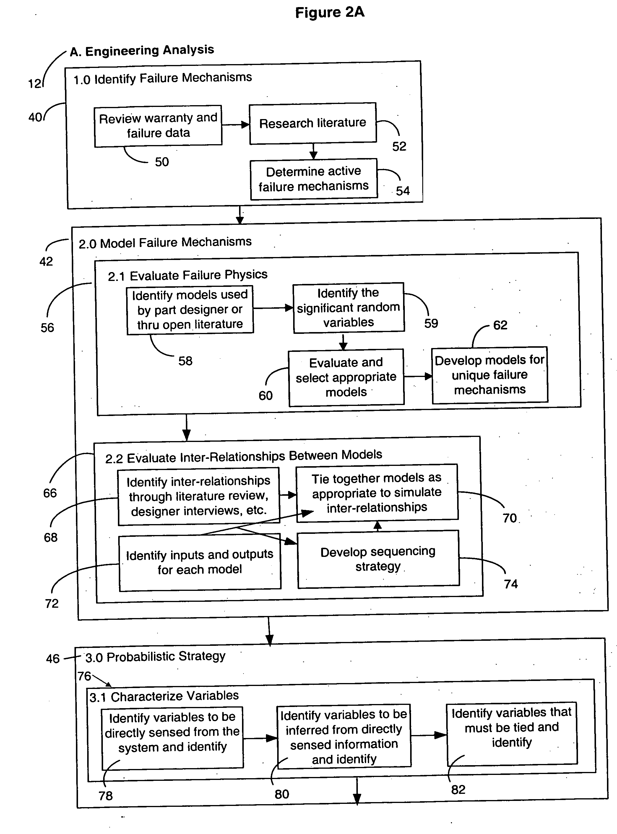
[0014] An advantage of one embodiment of the invention is that it divides system variables into three types: directly sensed—those that change during operation or product use; referred—those that do not (significantly) change during operation or product use; and inferred—those that change during operation or use but are not directly sensed. This strategy divides the probabilistic approach into two broad categories, pre-process off-board analysis and near real time on-board or off-board analysis, allowing for prediction of a probability of failure based on immediate and historic use.

Problems solved by technology

Failure can result from a number of mechanisms or combination of mechanisms.

Method used


Image

  • Method and apparatus for predicting failure in a system
  • Method and apparatus for predicting failure in a system
  • Method and apparatus for predicting failure in a system

Examples


example 1

[0063] The following example describes the modeling and prediction of failure in an exemplary embodiment according to the present invention.

[0064] FIGS. 5(a)-5(f) illustrate a preferred embodiment of the invention applied to a single dynamic component, namely a composite helicopter rotor hub. Reference numerals refer to the elements as they were discussed with respect to FIGS. 1-4. In this example engineering analysis step 12 first incorporates a probabilistic approach using response surface FPM 88 techniques. Thereafter, the same example is used to demonstrate any difference that response surface ST 90, direct FPM 92, or direct ST 94 would have yielded.

[0065] A helicopter rotor hub is a structure to which the blades of the helicopter are attached. The rotor hub is a composite laminate structure, which means that it is manufactured by laying plies of composite sheets together and joining them (with an adhesive resin) to form an integral structure. Each composite sheet is called a ...


PUM


Abstract

The invention regards a system reliability or failure predicting apparatus and method that incorporates known information about system component failure into a system model and uses the model with or without other acquired system data to predict the probability of system failure. An embodiment of the method includes using probabilistic methods to create a system failure model from the failure models of individual system components, predicting the failure of the system based on the component models and system data, ranking the sensitivity of the system to the system variables, and communicating a failure prediction.

Description

[0001] The patent claims priority pursuant to 35 U.S.C. § 119(e)1 to provisional application 60 / 260,449 filed Jan. 8, 2001.FIELD OF THE INVENTION [0002] This invention relates to a method and apparatus for predicting failure of a system. More specifically it relates to a method and apparatus for integrating data measured from a system, and / or data referenced from other sources, with component failure models to predict component or overall system failure. BACKGROUND OF THE INVENTION [0003] Any product will eventually fail, regardless of how well it is engineered. Often failure can be attributed to structural, material, or manufacturing defects, even for electronic products. A failure at the component or sub-component level often results in failure of the overall system. For example, cracking of a piston rod can result in failure of a car, and loss of a solder joint can result in failure of an electronic component. Such failures present safety or maintenance concerns and often result ...

Claims


Application Information

Patent Timeline
IPC IPC(8): G06F11/30G06F11/00H04L12/24
CPCG06F11/008G06F17/5018G06F2217/10H04L41/5032H04L41/06H04L41/16H04L41/5009G06F2217/44G06F30/23G06F2111/08G06F2113/26
Inventor TRYON, ROBERT G. IIIDOY, ANIMESHNASSER, A. LORENZ
Owner VEXTEC CORP
Learn More