
Simplified stereotaxtic brain surgery device, and band used for determining position at which such device is mounted on patient head

a stereotaxtic brain and surgery device technology, applied in the field of simplified stereotaxtic brain surgery devices and band used for determining positions, can solve the problems of complex configuration, hygienic problems of komai-type devices, and disadvantages in safety, and achieves superior handling properties and safety, and is easy to manufacture and inexpensive.

Inactive Publication Date: 2006-01-12
TAI HIROYUKI
View PDF4 Cites 7 Cited by
  • Summary
  • Abstract
  • Description
  • Claims
  • Application Information

AI Technical Summary

Benefits of technology

[0006] It is an object of the present invention to provide a simplified stereotactic brain surgery device that can be manufactured easily and inexpensively, and that is hygienic with superior handling properties and safety, and moreover to provide a band that is used to determine the position where this device is mounted to a patient's head.

Problems solved by technology

The Komai-type devices had hygienic problem, because it is necessary to mount the device from the stage of taking the CT images prior to surgery.
This device requires for example an arc-shaped frame for the puncturing with a puncturing needle from the desired direction, which made its configuration complex.
Furthermore, there were also disadvantages with regard to safety.

Method used


Image

  • Simplified stereotaxtic brain surgery device, and band used for determining position at which such device is mounted on patient head
  • Simplified stereotaxtic brain surgery device, and band used for determining position at which such device is mounted on patient head
  • Simplified stereotaxtic brain surgery device, and band used for determining position at which such device is mounted on patient head

Examples


first modification example

[4-A]First Modification Example of the Device

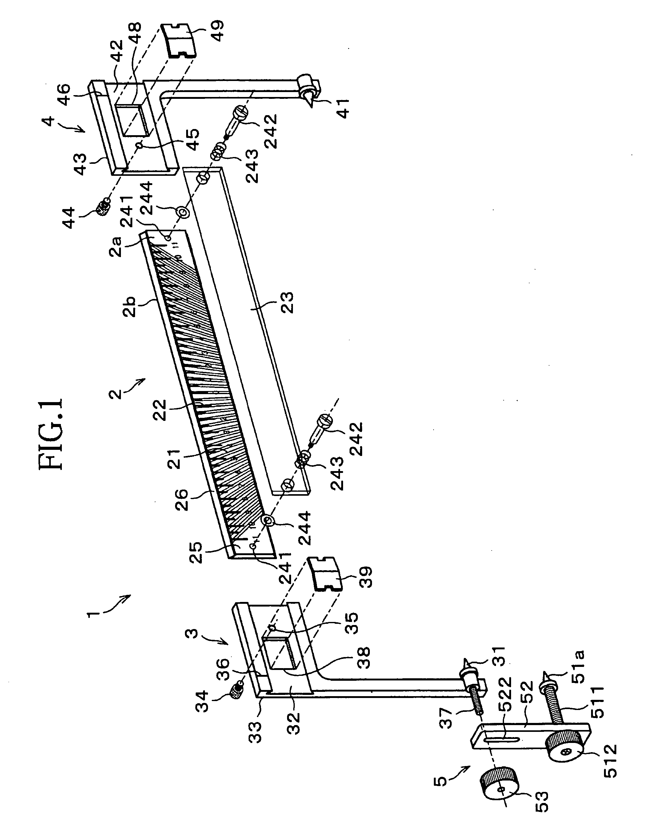
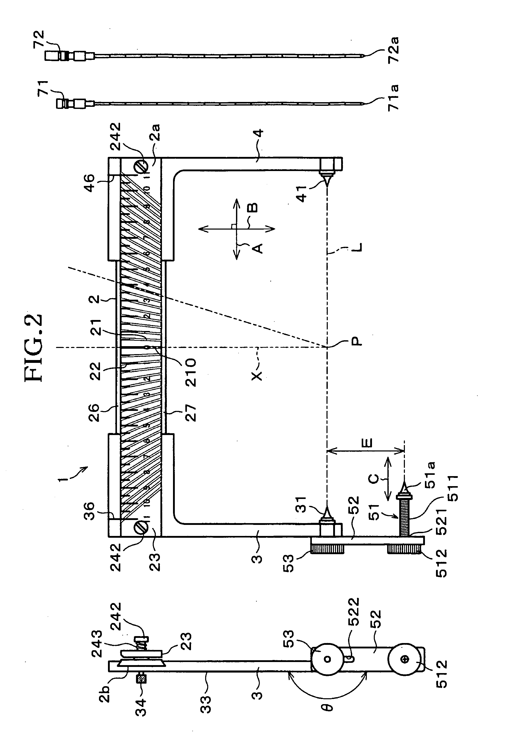
[0088]FIG. 17 is an exploded perspective view showing the overall configuration of a simplified stereotactic brain surgery device 100 (referred to below simply as “device 100”) in accordance with another embodiment of the present invention. It should be noted that to simplify explanations, portions that are the same as in the configuration of the above-described device 1 are marked by the same numerals, and their further explanation has been omitted.

[0089] In the device 100, the fixing needles 31 and 41 are fastened from both sides by left and right fixing needle fastening knobs 311 and 411. That is to say, male threaded portions are provided on the outer circumference of shafts 312 and 412 of the fixing needles 31 and 41, female threaded portions are provided on the inner circumference of fitting holes 313 and 413 of the fixing frames 3 and 4, the two are screwed together, and fixing needle fastening knobs 311 and 411 are attached to th...

second modification example

[4-B]Second Modification Example of the Device

[0097] It is also possible to apply the following modifications to the device 1, 100.

[0098] In the device 1, 100, the guide grooves 21 are engraved as guiding depressions in the frame 2 with puncture guides, but there is no limitation regarding the number, depth, width, length and profile shape of the guide grooves 21, as long as the puncturing needles 71 and 72 can be guided by those grooves. For example, the number of the guide grooves 21 provided on the frame 2 with puncture guides may also be lower than in the configurations of the above-described embodiments. Also, in the above-described embodiment, the diameter of the outer cylinders of the puncturing needles 71 and 72 is 2 mm and 3 mm, respectively, and in this case, it is preferable that the depth of the guide grooves 21 is about 0.6 mm to 1.4 mm, and that the width of the guide grooves 21 is about 1.5 mm to 3 mm. Thus, the preferable depth and width of the guide grooves 21 diff...


PUM


Abstract

A simplified stereotactic brain surgery device (1) comprises a frame (2) with puncture guides for guiding the tip of a puncturing needle to a predetermined position within the brain, and right and left fixing frames (3, 4) respectively having fixing needles (31, 41) for fixing the device (1) on the patient head, the fixing frames (3, 4) being displaceable in a longitudinal direction of the frame (2), and the frame (2) being provided with a plurality of guide grooves (21) for guiding the tip of a puncturing needle toward a point on a line connecting the right and left fixing needles (31, 41).

Description

TECHNICAL FIELD [0001] The present invention relates to simplified stereotactic brain surgery devices used for surgery on cerebral diseases such as hypertensive cerebral hemorrhages, brain tumors, brain abscesses, hydrocephalus, or cerebral cysts, and to bands used for determining the position at which such a device is mounted on a patient's head. BACKGROUND ART [0002] Conventionally, so-called Komai-type CT stereotactic brain surgery devices (referred to as “Komai-type devices” in the following) are known as stereotactic brain surgery devices (see Document 1 below, for example). The Komai-type devices had hygienic problem, because it is necessary to mount the device from the stage of taking the CT images prior to surgery. [0003] Document 1: Hiroshi Abe, Ryuichi Tanaka, Kimiyoshi Hayakawa, Haruhiko Kikuchi, Takashi Tsubokawa, Satoru Matsumoto (ed.) “NOUSHINKEIGEKASHIKKAN-NO SHUJUTSU TO TEKIOU II” (“Surgery of Neurosurgical Diseases and its Application II”), Asakura Shoten, Oct. 15, ...

Claims


Application Information

Patent Timeline
IPC IPC(8): A61B19/00A61B6/00
CPCA61B19/201A61B6/501A61B6/4423A61B90/11
Inventor TAI, HIROYUKI
Owner TAI HIROYUKI
Learn More