
Data multiplexing method and data multiplexer, and data transmitting method and data transmitter

a data multiplexing and data multiplexing technology, applied in the field of interleaving techniques, can solve problems such as high level noise in received pilot signals, code errors such as burst errors, and ineffective process performance, and achieve the effect of improving data transmission quality

Inactive Publication Date: 2006-01-12
NTT DOCOMO INC
View PDF18 Cites 10 Cited by
  • Summary
  • Abstract
  • Description
  • Claims
  • Application Information

AI Technical Summary

Benefits of technology

The present invention provides an effective data multiplexing method and a data multiplexer that improve data transmission quality by distributing multiplexing bits properly and flattening data quality in a frame. The invention also includes an interleaving process that can be performed using an interleaver with a large number of columns, which simplifies the process of multiplexing and reduces hardware size. The invention also includes a method for transmitting data signals using a bursty sending method and a method for regenerating reference phase in each timing of modulated data signals. Overall, the invention improves data transmission quality and simplifies the process of data transmission.

Problems solved by technology

In a digital transmission of a mobile communication system and the like, due to a multipath fading caused by reflection by a building and the like, the level of a receiving signal changes by large amounts temporally so that code errors such as burst errors occur.
Therefore, there is a problem in that the process is not performed effectively.
In the data transmit / receive method using the above-mentioned interpolation pilot signal, when S / N of the transmission line is low so that transmission quality is bad, high level noise is superimposed in received pilot signals.
Thus, large error is included in a phase measuring result by using the pilot signal PS.
Therefore, near the pilot signal PS, noise is not uniformed so that estimation error becomes large.
Thus, there is a problem in that, when data signals are placed adjacent to the pilot signal PS of the head part, a large influence is exerted on the phase so that the transmission quality is deteriorated.
However, an interleaving method applicable for flattening data quality in a flame when data bits are interleaved is not disclosed.

Method used


Image

  • Data multiplexing method and data multiplexer, and data transmitting method and data transmitter
  • Data multiplexing method and data multiplexer, and data transmitting method and data transmitter
  • Data multiplexing method and data multiplexer, and data transmitting method and data transmitter

Examples


Embodiment Construction

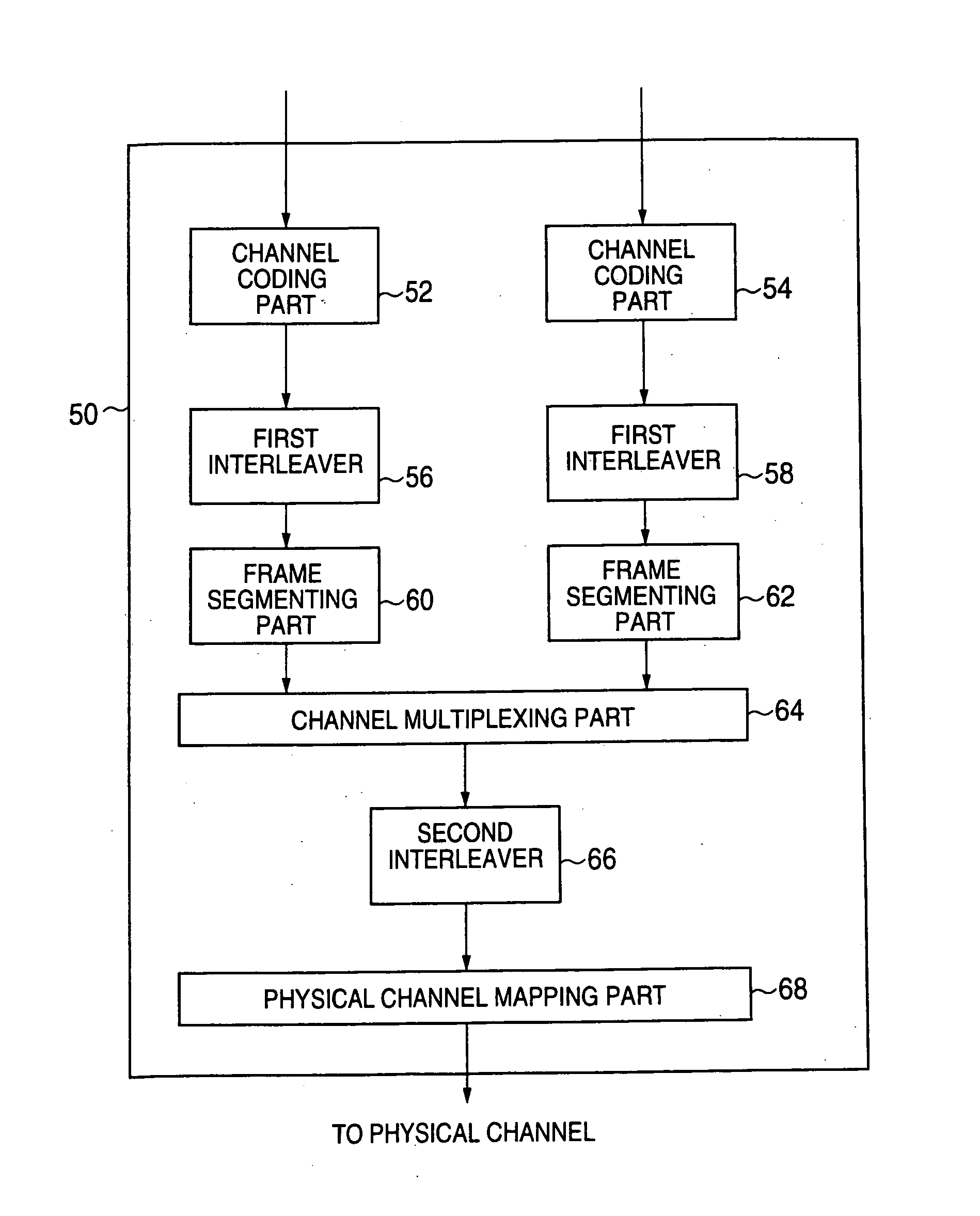
[0130]FIG. 4 is a block diagram of a data multiplexer 50 according to an embodiment of the present invention which corresponds to the first object. The data multiplexer 50 includes channel coding parts 52, 54, first interleavers 56, 58, frame segmenting parts 60, 62, a channel multiplexing part 64, a second interleaver 66 and a physical channel mapping part 68.

[0131] In the figure, the channel coding part 52, the first interleaver 56 and the frame segmenting part 60 perform an interleaving process of the logical channel A. The channel coding part 54, the first interleaver 58 and the frame segmenting part 62 perform an interleaving process of the logical channel B. Next, the operation of the data multiplexer 50 will be described by using a data flow which is input from the logical channel A. The following description also apply to a data flow input from the logical channel B.

[0132] The channel coding part 52 performs a channel coding process on data input by the logical channel A. ...


PUM


Abstract

An effective data multiplexing method wherein an error correction ability is exerted at the maximum so that data transmission quality is improved and a data transmitting method in which an interleaving process applicable to data transmission using interpolation pilot signal is performed are provided. The data multiplexing method includes the steps of: coding input data for each input channel; multiplexing said data which is coded; performing an interleaving process on said data which is multiplexed; and outputting said data. In the data transmitting method, when an interleaving process is performed, an interleaver is used in which the number of columns of the interleaver is twice as many as the number of slots of a frame.

Description

TECHNICAL FIELD [0001] The present invention relates to an interleaving technique for improving an ability of error correcting code against a burst error. More particularly, the present invention relates a method and an apparatus for multiplexing channels by using an interleaving method in which randomness of data is increased so that an effect of interleaving is improved. [0002] In addition, the present invention relates to a data transmitting method which is used applicably in combination with a data receiving method of performing synchronous detection by using an interpolation pilot signal. BACKGROUND ART [0003] In a digital transmission of a mobile communication system and the like, due to a multipath fading caused by reflection by a building and the like, the level of a receiving signal changes by large amounts temporally so that code errors such as burst errors occur. Thus, various error correcting codes are used. In the error correcting codes, an interleaving technique is use...

Claims


Application Information

Patent Timeline
Patent Type & Authority Applications(United States)
IPC IPC(8): H04B7/216H03M13/27H04L1/00
CPCH03M13/271H03M13/2789H03M13/2792H04L1/004H04L27/22H04L1/0071H04L1/0078H04L25/023H04L27/20H04L1/0041H03M13/27
Inventor OKUMURA, YUKIHIKOANDO, HIDEHIRO
Owner NTT DOCOMO INC
Learn More