
Apparatus and method for efficiently fabricating, dismantling and storing a porous tubular windblown particle control device

a technology of windblown particle control and apparatus, which is applied in the direction of excavation, protective construction, construction, etc., can solve the problems of reducing visibility, icy roads, hazardous driving conditions, etc., and achieves the effects of reducing visibility, reducing labor intensity, and reducing labor intensity

Inactive Publication Date: 2006-01-05
TABLER RONALD D
View PDF52 Cites 8 Cited by
  • Summary
  • Abstract
  • Description
  • Claims
  • Application Information

AI Technical Summary

Benefits of technology

[0012] The present invention is directed to a very effective porous tubular windblown particle control device which is fabricated relatively inexpensively and quickly from relatively inexpensive and readily-available materials. The nature and configuration of the windblown particle control device allows it to be positioned and erected quickly and efficiently, and to be dismantled in an equally quick and efficient manner. The ability to quickly and efficiently erect and dismantle the windblown particle control devices offers a realistic opportunity for it to be dismantled completely during those times of the year when it is not needed, or to be dismantled and then reassembled at a different position to obtain optimum windblown particle control effects on critical areas such as roadways or railroad tracks. Furthermore, the nature of the materials from which the control device is fabricated permit those materials to be transported and stored efficiently without consuming a large amount of storage space. The nature of the materials from which the control device is constructed are not bulky or heavy, thereby allowing those materials to be transported conveniently to and from the location of use. A lesser number of persons are required to fabricate and erect the control devices, or the control devices can be erected more quickly with the same number of people. The convenience of dismantling and storing the windblown particle control devices reduces or eliminates the principal reasons for permitting an aesthetic obtrusion to the natural environment during those portions of the year when the control devices are not needed. The relatively low expense of the materials necessary to fabricate the control device, and the relatively low costs of erecting and dismantling the control device, and the convenience of storing the materials when the control device is not needed, facilitate the use of the windblown particle control device in circumstances which were not previously considered as advantageous, such as for accumulating snow in agricultural fields to increase the soil moisture content for growing crops, retaining the topsoil against wind erosion, and shielding immature plants from the shear stress of wind and from the rapid evaporation of soil moisture at their critical early-growth stages.
[0013] These and other beneficial improvements, uses, effects and consequences of the present invention are realized in a windblown particle control device which, when attached to the surface of the earth, stabilizes particle cover and controls deposition and retention of windblown particles. The windblown particle control device comprises a sheet of netting material curved in an arched configuration to establish a generally tubular cross-sectional shape upon contact with the earth surface. The sheet comprises a plurality of webs linked together to define apertures between the webs and through the sheet. The wind flowing through the apertures reduces in velocity and alters the turbulence effects to create aerodynamic effects which stabilize, deposit and retain the particles on the earth surface in a protected area. Frame structures may be attached to or made integral with the sheet of netting material to establish or help establish the sheet in the tubular configuration with respect to the earth surface.
[0014] The sheet may be connected to the frame structures by weaving a portion of the frame structures through apertures on opposite sides of webs within the sheet. The frame structures may be generally straight when woven through the apertures, and then bent to establish the arched configuration and tubular shape with respect to the earth. The sheet of netting material may have sufficient inherent strength to self-support and self-maintain the arched configuration to establish the generally tubular cross-sectional shape, in which case the frame structures are integral with the sheet. Geogrid, geotextile or cured synthetic composite material, such as fiberglass, may provide sufficient strength to self-support and self-maintain the sheet and the frame structures in the arched configuration.

Problems solved by technology

Windblown snow, sand, and dust can create hazardous driving conditions by reducing visibility and forming drifts on roadways to block or impede traffic movement.
Blowing snow also causes icy roads, which are a major cause of vehicle accidents.
Blowing snow also causes significant problems on railroads by forming drifts that block the passage of trains where tracks pass through cuts in hills, and by clogging switches and interfering with the operation of electronic sensors for detecting over-heated journals and dragging equipment.
The snow fence creates aerodynamic drag and alters the structure of the turbulence which slows the velocity of the wind and diminishes its capacity to carry snow.
Otherwise, the placement of the snow fence will be ineffective in preventing snow accumulation on the roadway or critical area.
Because of their relative massive, complex and sturdy nature, conventional snow fences are usually built in place at the location of use.
The bulky nature of the materials used to construct such snow fences usually makes their fabrication a time-consuming exercise.
In addition to being bulky, the construction materials are usually expensive and difficult to transport to the construction site of the snow fence.
The typical end result of constructing such snow fences is a collection of immobile, expensive and artificial structures which are visually obtrusive and aesthetically objectionable in a natural environment.
The cost of dismantling a snow fence is approximately the same as the considerable cost of fabricating the snow fence in the first place.
The time required to dismantle a snow fence may be slightly less than the time required to fabricate the snow fence in the first instance, but the time requirements are nevertheless considerable and significant.
The relatively permanent posts and anchoring structures used to hold the snow fence panels to the ground are usually not removable, even though the panels which create the aerodynamic effects might be removed from the anchoring posts and structures.
The amount of material and the transportation costs of those materials between the site of use and the storage location creates additional problems and difficulties.
The amount of space required to stow the numerous and bulky constituent materials of a typical wooden panel snow fence is substantial.
Use of that space for storage constitutes an additional cost associated with disassembling a snow fence and is therefore an added detriment to dismantling conventional snow fence during those times of the year when it is not needed.
Because of the negative impacts of the cost, obtrusiveness, fabrication, dismantlement, removal and storage issues described above, previous artificial snow fences and windblown particle control structures have not been used on a prevalent basis for other beneficial purposes such as accumulating snow in agricultural fields to increase the soil moisture content for growing crops, retaining the topsoil against wind erosion, or shielding immature plants from the shear stress of wind and from the rapid evaporation of soil moisture at their critical early-growth stages.
Many other disadvantages associated with the deployment of snow fences and windblown particle control devices are known and appreciated.

Method used


Image

  • Apparatus and method for efficiently fabricating, dismantling and storing a porous tubular windblown particle control device
  • Apparatus and method for efficiently fabricating, dismantling and storing a porous tubular windblown particle control device
  • Apparatus and method for efficiently fabricating, dismantling and storing a porous tubular windblown particle control device

Examples


Embodiment Construction

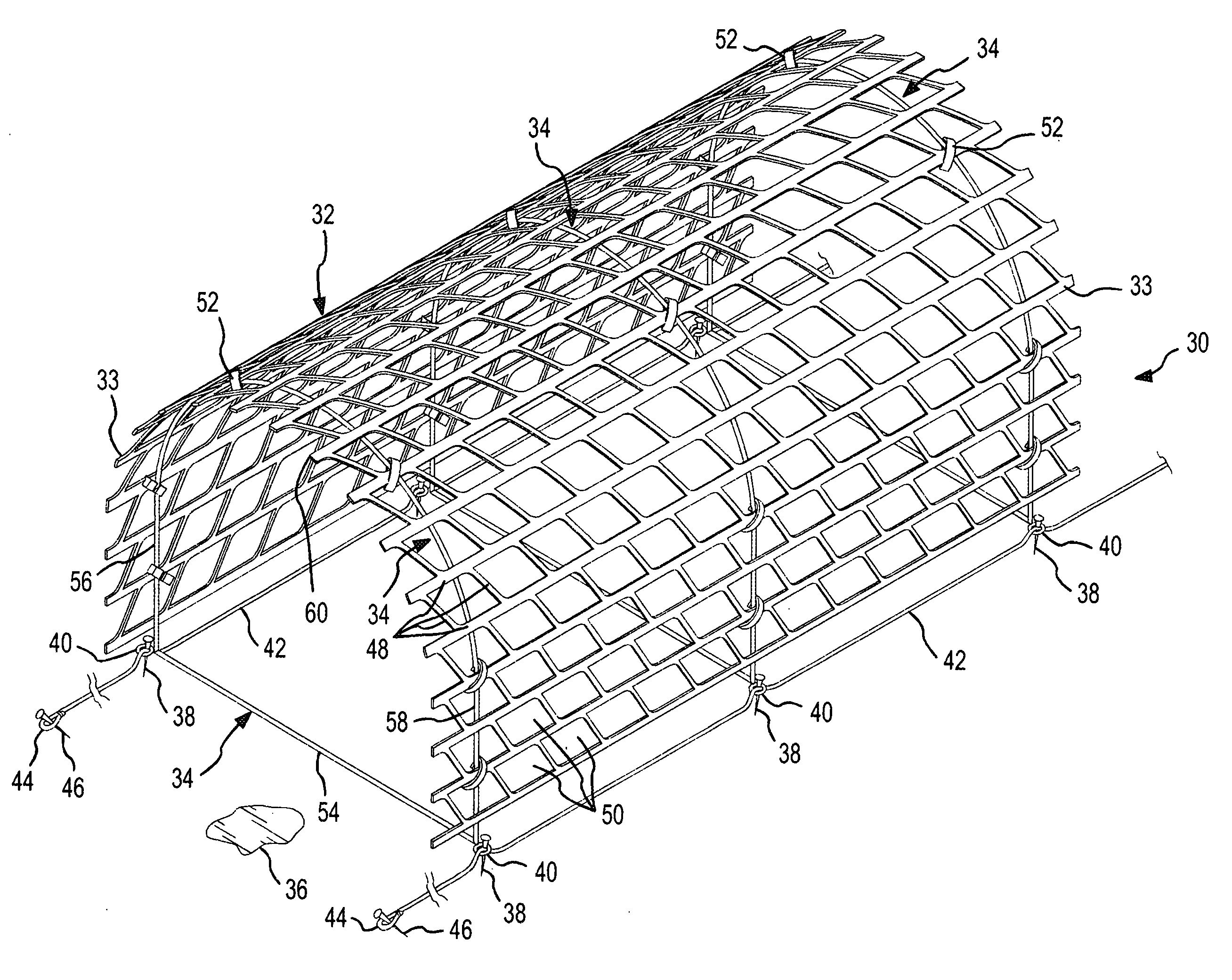
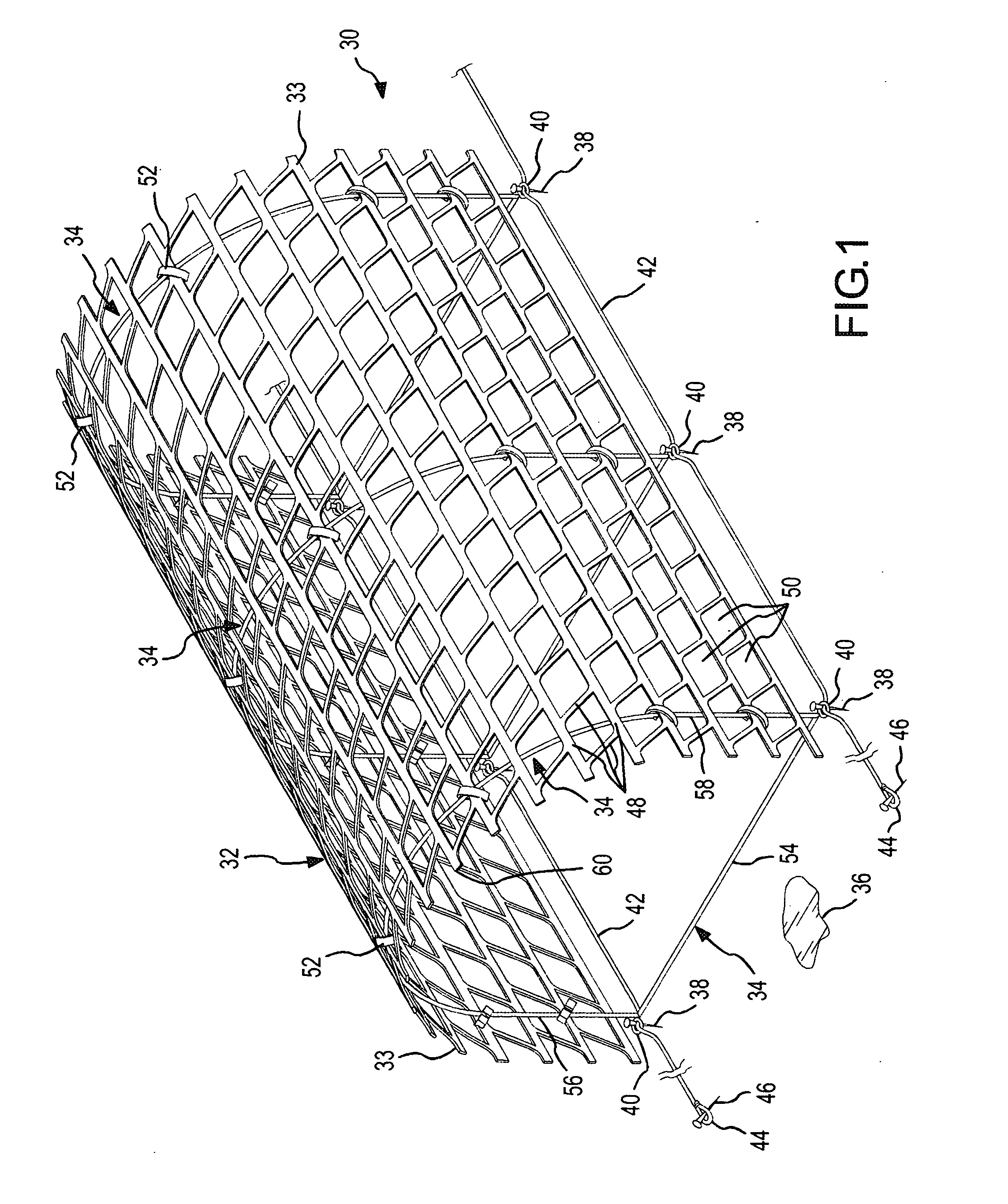
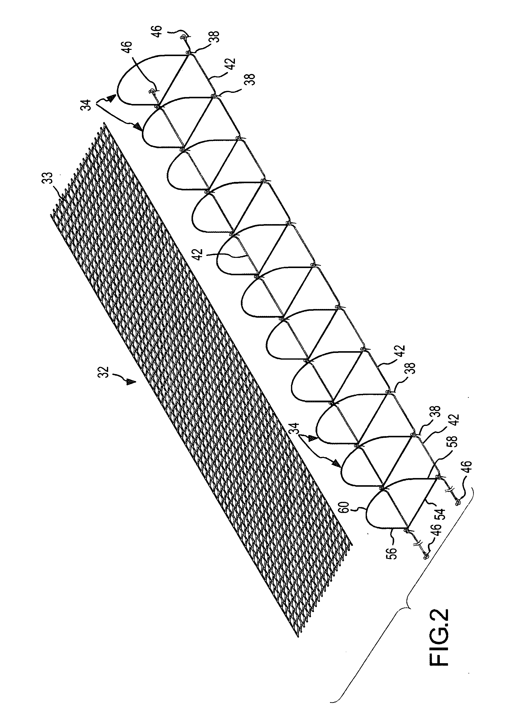
[0036] One form of a porous tubular windblown particle control device 30 incorporating the present invention is shown in FIGS. 1-3. The control device 30 is generally formed by a sheet 32 of conventional, flexible, plastic netting material 33 which is connected to and supported by a support structure formed from a plurality of D-shaped frame structures 34 that are longitudinally spaced apart from one another in a series along the length of the netting sheet 32. The strength of the sheet 32 of netting material 33 and the D-shaped frame structures 34 establish and maintain the general overall three-dimensional tubular shape and configuration of the device 30.

[0037] The device 30 is secured in a desired position on the earth surface or ground 36 or other earth surface by an anchor system which includes frame spikes 38 that are inserted through anchor elements or loops 40 formed in the frame structures 34. The frame spikes 38 are driven through the anchor loops 40 and into the ground 3...


PUM


Abstract

A windblown particle control device which, when attached to the surface of the earth assumes a generally tubular cross-sectional shape, stabilizes particle cover and controls deposition and retention of windblown particles. A sheet of netting material is curved in an arched configuration. Webs of the sheet are linked together to define apertures through the sheet. The apertures create aerodynamic effects in the wind which stabilize, deposit and retain the particles on the earth surface. A kit of components, which includes the netting sheet and a plurality of frame structures to support and maintain the netting sheet in the arched configuration may be employed to assemble the control device for use.

Description

CROSS-REFERENCE TO RELATED APPLICATION [0001] This is a continuation in part of an invention for a Porous Tubular Device and Method for Controlling Windblown Particle Stabilization Deposition and Retention, described in U.S. patent application Ser. No. 10 / 882,123, filed Jun. 30, 2004 by the inventor hereof. The subject matter of this prior-filed application is incorporated herein by this reference.FIELD OF THE INVENTION [0002] This invention relates to controlling the deposition and retention of windblown particles, such as snow, sand or soil. More particularly, the present invention relates to a new and improved windblown particle control device and method which utilizes a three-dimensional porous tubular configuration to effectively control the deposition, retention and stabilization of windblown particles, and further, which offers the advantages of relatively inexpensive fabrication, efficient assembly, easy deployment, quick dismantlement, and convenient and space-efficient sto...

Claims


Application Information

Patent Timeline
Patent Type & Authority Applications(United States)
IPC IPC(8): E02D17/20
CPCE01F7/02E02D17/20
Inventor TABLER, RONALD D.
Owner TABLER RONALD D
Learn More