Agitator and melting furnace with agitator

a technology of agitator and melting furnace, which is applied in the direction of furnaces, charge manipulation, manufacturing converters, etc., can solve the problems of low-pressure type furnaces that are not widely used, mechanical-type furnaces that do not have sufficient durability, and complicated operation and maintenance of them, so as to achieve good operability and low running cost

Active Publication Date: 2006-01-05
TAKAHASHI KENZO
View PDF6 Cites 12 Cited by
  • Summary
  • Abstract
  • Description
  • Claims
  • Application Information

AI Technical Summary

Benefits of technology

[0007] The present invention is proposed in consideration of the aforementioned current situation, and it is an object of the present invention to propose an agitator and a melting furnace which are not expensive, have good operability, can operate with a low running cost, and can surely melt an inputted material.

Problems solved by technology

The aforementioned mechanical-type furnaces do not have a sufficient durability since the rotational body is used to directly agitate a high-temperature melt.
Furthermore, there is a problem in that the operation and the maintenance thereof are complicated.
Low-pressure type furnaces are not widely used since the operability thereof is not so good.
Electromagnetic-type furnaces require a high current, thereby increasing power consumption, resulting in high running costs.
Furthermore, since the cooling of coils thereof requires great care, the cost of the entire equipment is inevitably increased, which hinders the widespread use thereof.

Method used


Image

  • Agitator and melting furnace with agitator
  • Agitator and melting furnace with agitator
  • Agitator and melting furnace with agitator

Examples


Embodiment Construction

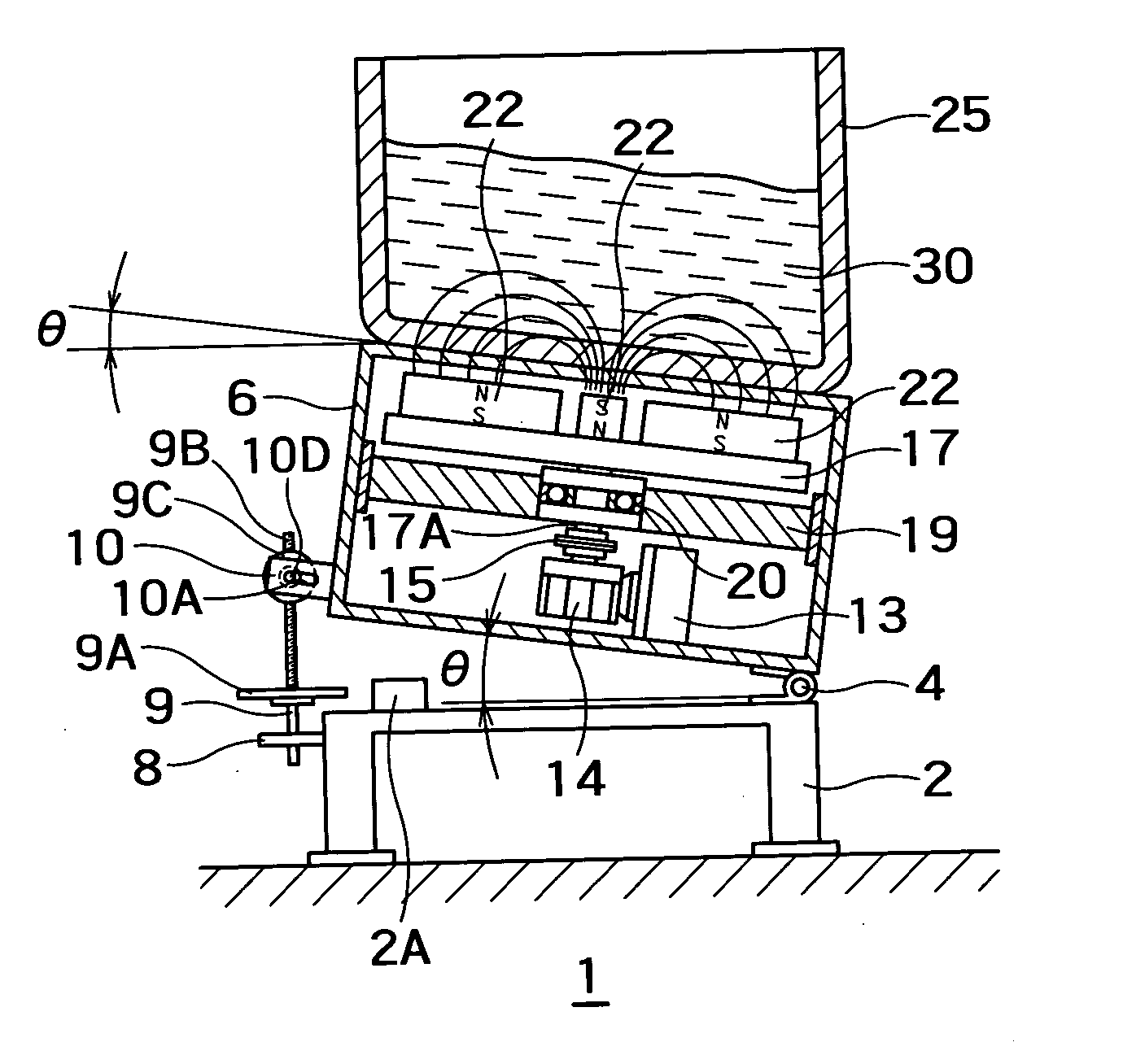
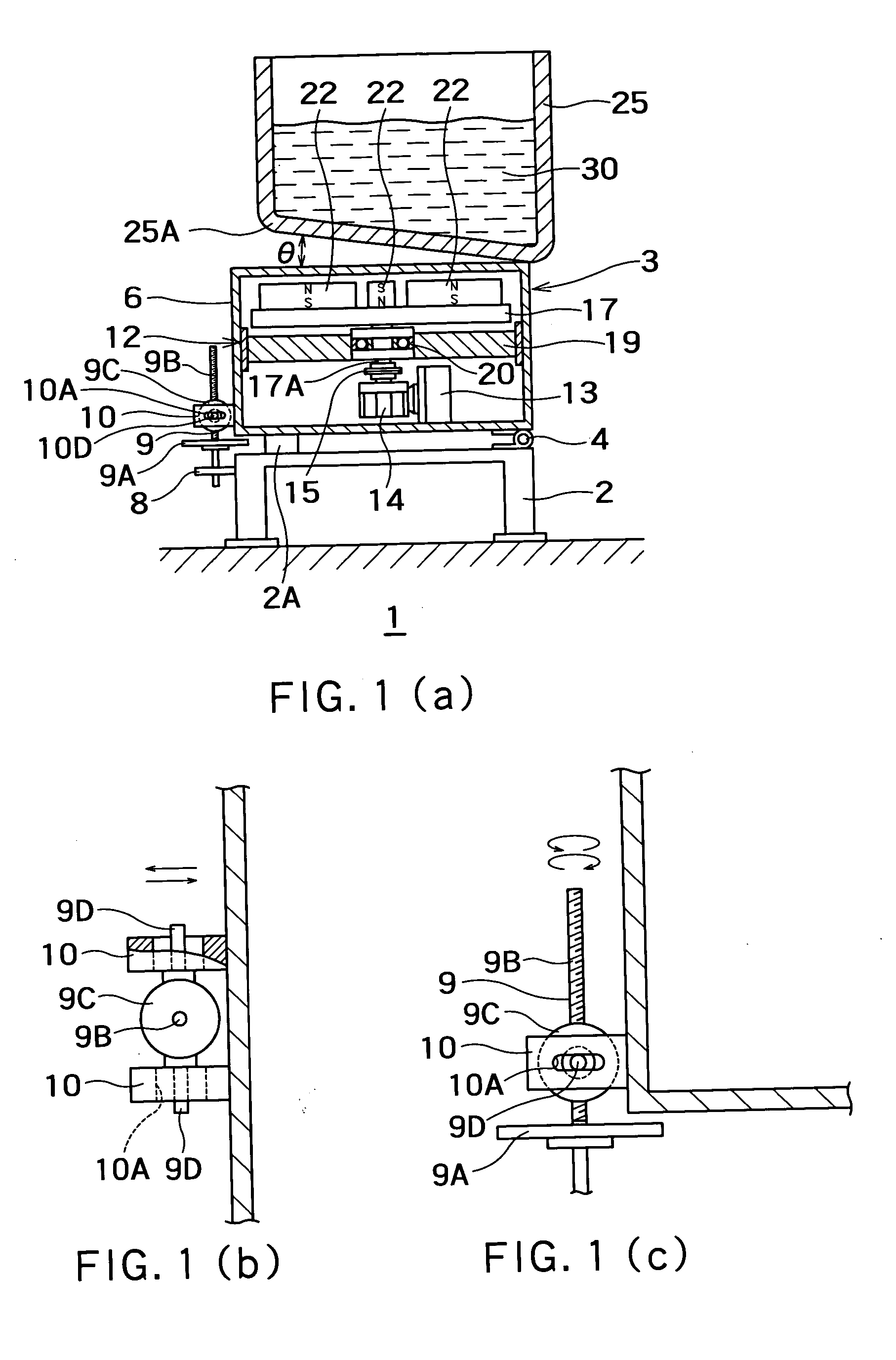
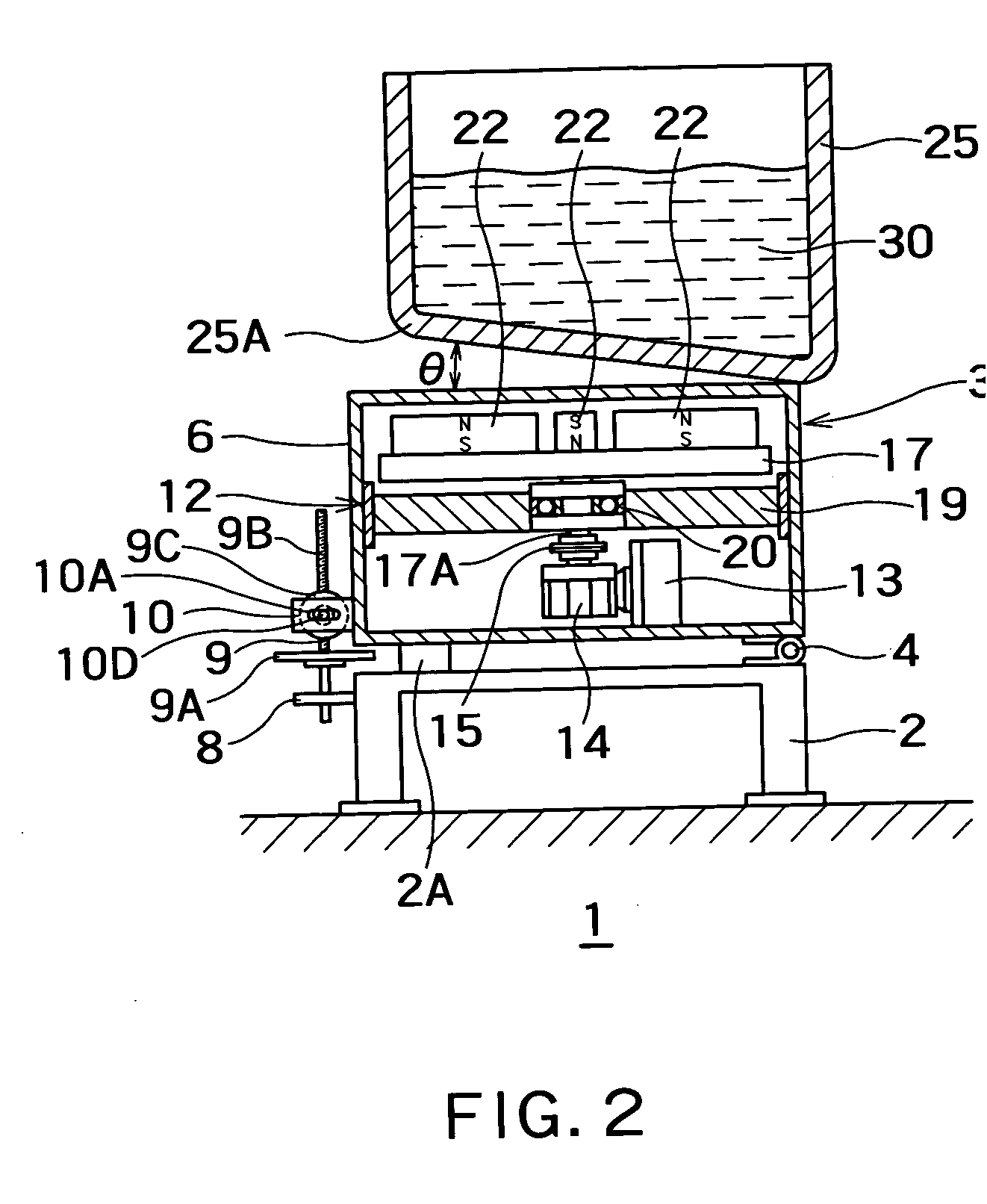
[0019]FIG. 1(a) shows an embodiment of the present invention in a non-use state, and FIG. 2 shows it in a use sate. FIGS. 1(b) and 1(c) are drawings obtained by enlarging a part of FIG. 1(a). FIG. 1(b) is a plan view viewing part of the apparatus of FIG. 1(a) from above, and FIG. 1(c) is a view viewing the part from the same direction as FIG. 1(a). In FIG. 1(a), a frame 2 is fixed on a floor 1. A magnetic field generating portion 3 is mounted on the frame 2 in such a manner that it is rotatable around a hinge 4, i.e., around a substantially horizontal axis extending in a direction perpendicular to the surface of the drawing paper, so as to be capable of moving up and down. That is to say, the magnetic field generating portion 3 has a hollow housing (support base) 6, which is mounted on the frame 2 so as to be capable of rotating to move up and down around the hinge 4, i.e., around a substantially horizontal axis, as can be understood from FIG. 1(a) and FIG. 2. Actually, the moving u...


PUM

PropertyMeasurementUnit
forceaaaaaaaaaa
angleaaaaaaaaaa
rotation speedaaaaaaaaaa

Abstract

An agitator for applying an alternating field to a melting furnace main body in order to melt a row material to form a melt includes a plurality of magnets, which are arranged so that magnetic lines of force emitted from one of the magnets pass through the melt in the melting furnace main body and return to another magnet, the magnets being fixed to an inclined surface which is inclined by an angle with respect to a horizontal surface, and being rotatable around an axis substantially perpendicular to the inclined surface.

Description

CROSS-REFERENCE TO RELATED APPLICATION [0001] This application is based upon and claims the benefit of priority from prior Japanese Patent Application No. 2004-193875, filed on Jun. 30, 2004, the entire contents of which are incorporated herein by reference. BACKGROUND OF THE INVENTION [0002] 1. Field of the Invention [0003] The present invention relates to an agitator and a melting furnace with an agitator. [0004] 2. Background Art [0005] Conventionally, among melting furnaces for melting, for example, aluminum for the purpose of recycling, aluminum melting furnaces with agitators can be classified into those of a mechanical type, which insert a rotational body into a furnace in order to directly agitate aluminum, those of a low-pressure type, which use a negative pressure pump to suck up melt to agitate it, and those of an electromagnetic type which generate a shifting magnetic field by causing a three-phase alternating current to flow through a fixed electrode and electromagnetic...

Claims


Application Information

Patent Timeline
Patent Type & Authority Applications(United States)
IPC IPC(8): C21C7/00B01F13/08C21C1/06C22B4/08C22B9/02F27B3/06F27D3/00F27D27/00H05B6/34
CPCF27D2003/0039F27D27/00
Inventor TAKAHASHI, KENZO
Owner TAKAHASHI KENZO
Why Eureka
Try Eureka