
Optical disk and optical disk apparatus

a technology of optical disk and optical disk, which is applied in the direction of optical record carriers, instruments, data recording, etc., can solve the problems of inhibiting the generation of amplitude in te signals, and achieve the effect of reliably reading

Inactive Publication Date: 2005-12-29
PANASONIC CORP
View PDF6 Cites 4 Cited by
  • Summary
  • Abstract
  • Description
  • Claims
  • Application Information

AI Technical Summary

Benefits of technology

[0015] Therefore, with the foregoing in mind, it is an object of the present invention to provide an optical disk and an optical disk apparatus by which an address signal can be read reliably even at a region where a recording mark is formed so as to lie over an address pre-pit after recording, not to mention before recording.

Problems solved by technology

In the conventional optical disk and optical disk apparatus as described above, there has been a problem as follows.
In particular, in the case of high-speed recording in an optical disk of a disk format such as DVD-R, the recording mark is liable to expand, which may cause the recording mark to cover the pre-pit 5A entirely, thereby further inhibiting the generation of amplitude in the TE signal.

Method used


Image

  • Optical disk and optical disk apparatus
  • Optical disk and optical disk apparatus
  • Optical disk and optical disk apparatus

Examples


first embodiment

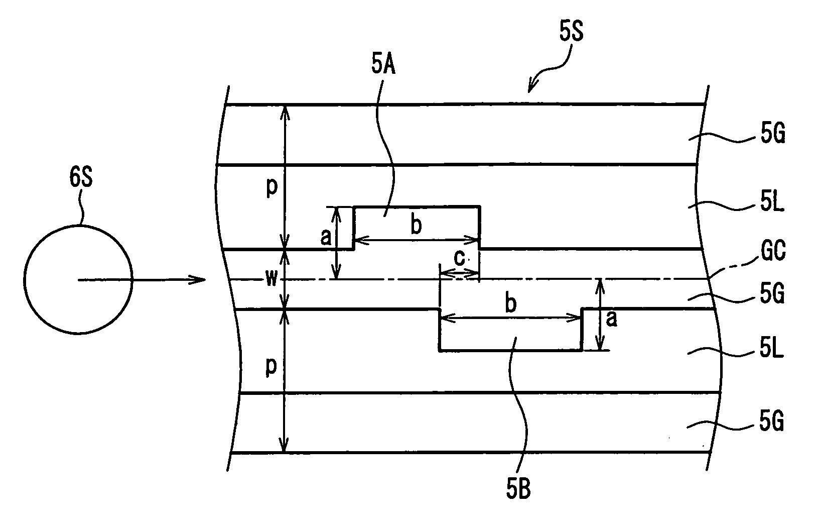
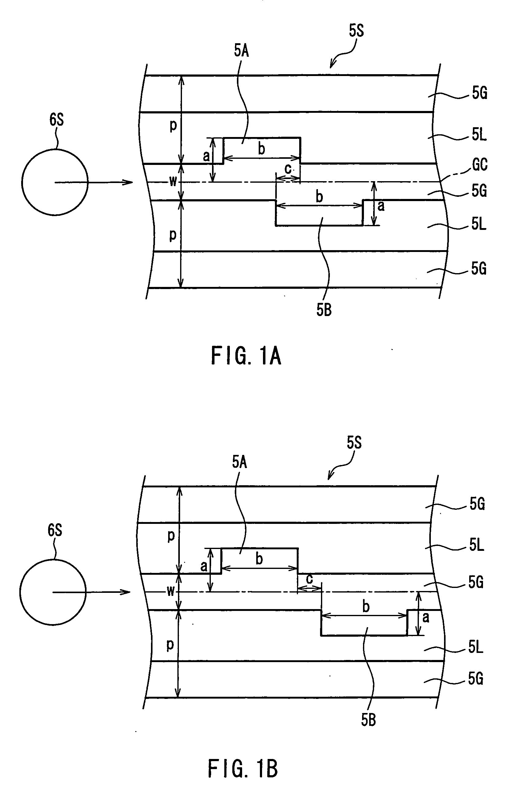
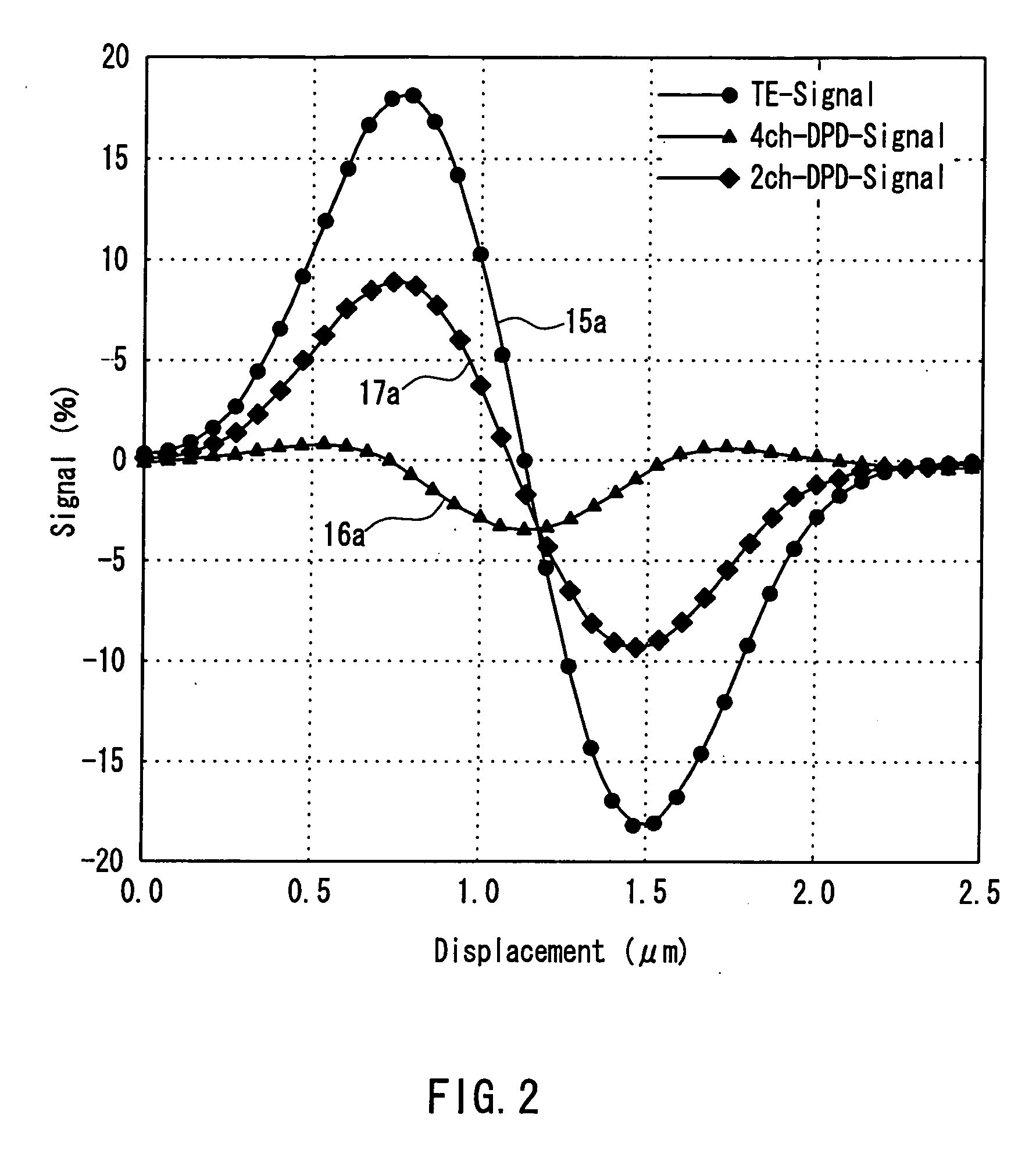
[0047] A first embodiment of the present invention will be described with reference to FIGS. 1 to 4. The basic configuration of an optical disk apparatus according to the present embodiment is the same as that of the conventional optical disk apparatus shown in FIG. 10A. Also, the state where a light spot scans a signal surface of an optical disk is the same as that shown in FIG. 10B, and the form of a light spot detected on a photodetector is the same as that shown in FIG. 10C. Therefore, the following description is made with reference to these drawings. The elements identical to those used in the conventional example are described using the same reference numerals and duplicate explanations will be omitted.

[0048] In the present embodiment, a DPD signal is used to detect an address signal of an optical disk regardless of the presence or absence of a hologram 9.

[0049]FIG. 1A and FIG. 1B are plan views showing shapes of an address signal pre-pit of the optical disk according to th...

second embodiment

[0059] Hereinafter, a second embodiment of the present invention will be described with reference to FIGS. 5 to 7. The elements identical to those used in the first embodiment are described using the same reference numerals. An optical disk apparatus of the present embodiment is identical to that of the first embodiment except that the shape of an address signal pre-pit of an optical disk is different, and thus duplicate explanations will be omitted here. In the present embodiment, a DPD signal is used to detect an address signal of an optical disk as in the first embodiment.

[0060]FIG. 5 is a plan view showing the shape of an address signal pre-pit of an optical disk according to the present embodiment. In FIG. 5, the address signal pre-pit 5A1 has the same height as the guide groove 5G and protrudes from the guide groove 5G toward the region of the land portion 5L on one side, with the amount of protrusion measured from the center line GC of the guide groove 5G being “a1”. Further...

third embodiment

[0067] Hereinafter, a third embodiment of the present invention will be described with reference to FIGS. 8 and 9. The elements identical to those used in the first embodiment are described using the same numerals. An optical disk apparatus of the present embodiment is identical to that of the first embodiment except that the shape of an address signal pre-pit of an optical disk is different, and thus duplicate explanations will be omitted here. In the present embodiment, an address signal of the optical disk is detected based on a TE signal in an unrecorded region, whereas an address signal is detected based on either one of a TE signal and a DPD signal in a recorded region.

[0068] An address signal pre-pit of the present embodiment has the same shape as that of the conventional example shown in FIG. 11, though the size thereof is different from that of the conventional example shown in FIG. 11. Thus, the address signal pre-pit of the present embodiment will be described with refer...


PUM


Abstract

An optical disk according to the present invention includes: a substrate in a disk shape; guide grooves arranged at a pitch p in a radial direction of the substrate, each of the guide grooves being formed so as to extend in a circumferential direction of the substrate; and a pre-pit formed in a space between the guide grooves so as to extend along the guide groove. The optical disk is configured so that an address signal assigned to each location on a signal surface is indicated by the arrangement of the pre-pit in accordance with a predetermined rule. The pre-pit is composed of a pair of pre-pits formed on respective sides of the guide groove. The pair of pre-pits are arranged so as to be displaced in the circumferential direction so that a distance between inner edges of the respective pre-pits in the circumferential direction is smaller than the pitch p of the guide grooves. An optical disk apparatus of the present invention detects light reflected from the optical disk configured as above, calculates a differential phase detection signal, and detects an address signal using the differential phase detection signal. According to this optical disk apparatus, an address signal can be read reliably even at a region where a recording mark is formed so as to lie over the address pre-pit.

Description

BACKGROUND OF THE INVENTION [0001] 1. Field of the Invention [0002] The present invention relates to an optical disk used as a medium for recording information and also to an optical disk apparatus for recording / reproducing information on / from the optical disk. [0003] 2. Description of Related Art [0004] As a conventional technique for detecting an address signal on a signal surface of an optical disk, the technique described in “DVD Specifications for DVD-R for General, Physical Specifications Version 2.0” is known, for example. This conventional technique will be described with reference to FIGS. 10A to 10D, FIG. 11, and FIG. 12, which schematically show this technique. [0005]FIG. 10A shows the basic configuration of a conventional optical disk apparatus. FIG. 10B is a plan view showing the state where a light spot scans a signal surface of an optical disk. FIG. 10C is a plan view showing one form of a light spot detected on a photodetector. FIG. 10D is a plan view showing another...

Claims


Application Information

Patent Timeline
IPC IPC(8): G11B7/007G11B7/013G11B7/24
CPCG11B7/24079G11B7/24085G11B7/24082
Inventor NISHIWAKI, SEIJIYAMAGUCHI, HIROYUKIDEGUCHI, HIRONORI
Owner PANASONIC CORP
Learn More