
Downhole Drilling Network Using Burst Modulation Techniques

a technology of burst modulation and data transmission, which is applied in the field of oil and gas drilling, can solve the problems of limiting the number and types of devices that could be connected to the network, unable many attempts to create such a system have failed to achieve significant commercial acceptance, so as to achieve efficient allocation of bandwidth, efficiently acquiring and receiving signals, and effectively sharing bandwidth

Active Publication Date: 2005-12-29
INTELLISERV
View PDF70 Cites 83 Cited by
  • Summary
  • Abstract
  • Description
  • Claims
  • Application Information

AI Technical Summary

Benefits of technology

[0010] In view of the foregoing, the present invention relates to apparatus and methods for effectively allocating bandwidth in high-speed downhole telemetry systems. The present invention further relates to apparatus and methods for effectively sharing bandwidth between downhole devices that transmit data in an inconsistent or intermittent manner. Finally, the present invention relates to apparatus and methods for efficiently acquiring and receiving signals that are transmitted intermittently or sporadically in order to conserve or effectively use bandwidth.

Problems solved by technology

However, due to the complexity, expense, and unreliability of such systems, many attempts to create such a system have failed to achieve significant commercial acceptance.
That is, as is currently the case in most transmission systems, bandwidth is limited by the communication hardware involved.
Moreover, although the technology described in the Hall patent is a colossal improvement over prior telemetry systems, it is conceivable that the vast array of downhole tools and sensors used in downhole drilling could generate enough data to consume most of the available bandwidth, thereby significantly limiting the number and types of devices that could be connected to the network.
In some cases, bandwidth may be unnecessarily consumed due to inefficient bandwidth allocation.
For example, bandwidth may be consumed by needlessly transmitting raw data over the network at times or in quantities that are not needed.

Method used


Image

  • Downhole Drilling Network Using Burst Modulation Techniques
  • Downhole Drilling Network Using Burst Modulation Techniques
  • Downhole Drilling Network Using Burst Modulation Techniques

Examples


Embodiment Construction

[0029] It will be readily understood that the components of the present invention, as generally described and illustrated in the Figures herein, could be arranged and designed in a wide variety of different configurations. Thus, the following more detailed description of embodiments of apparatus and methods of the present invention, as represented in the Figures, is not intended to limit the scope of the invention, as claimed, but is merely representative of various selected embodiments of the invention.

[0030] The illustrated embodiments of the invention will be best understood by reference to the drawings, wherein like parts are designated by like numerals throughout. Those of ordinary skill in the art will, of course, appreciate that various modifications to the apparatus and methods described herein may easily be made without departing from the essential characteristics of the invention, as described in connection with the Figures. Thus, the following description of the Figures ...


PUM


Abstract

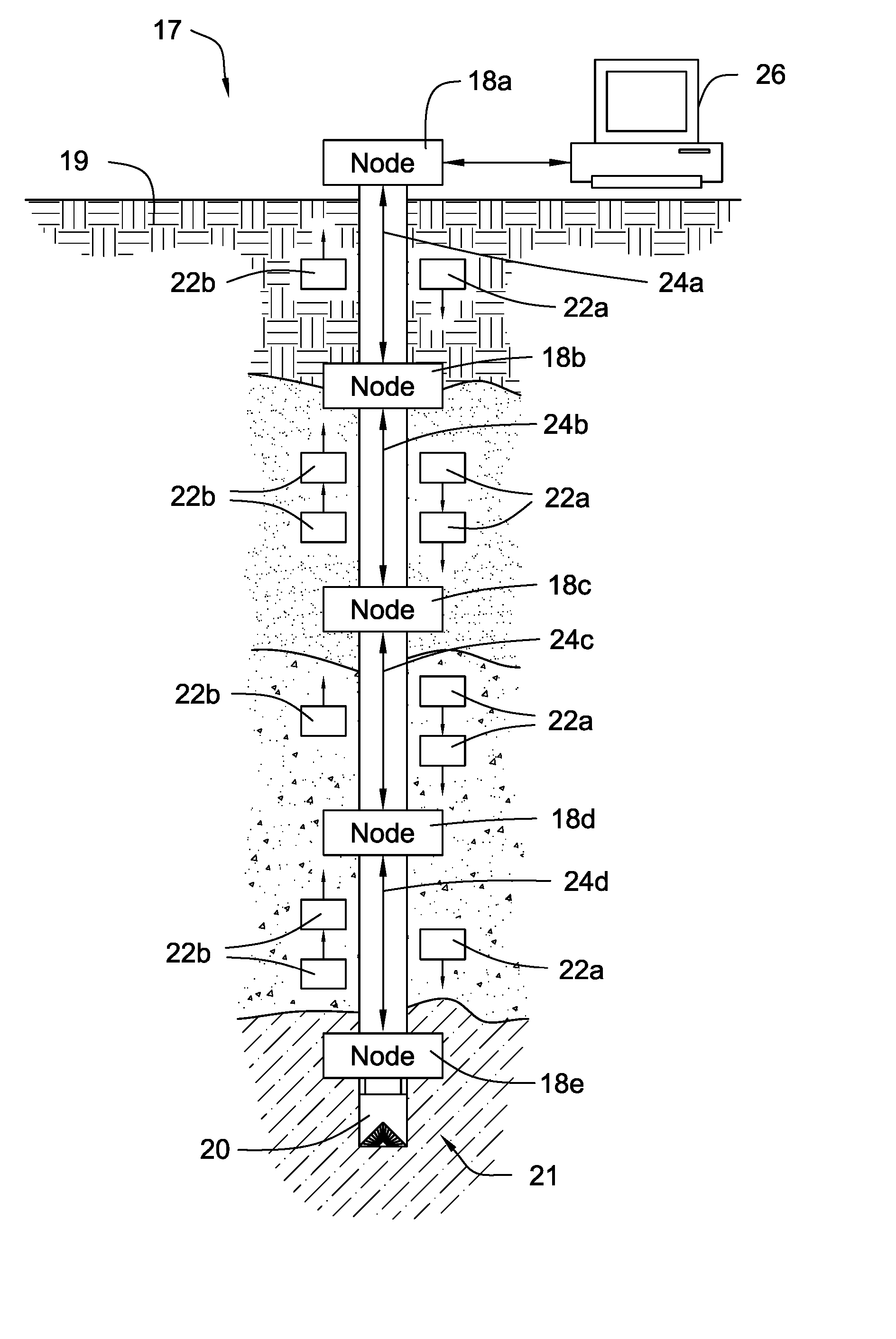
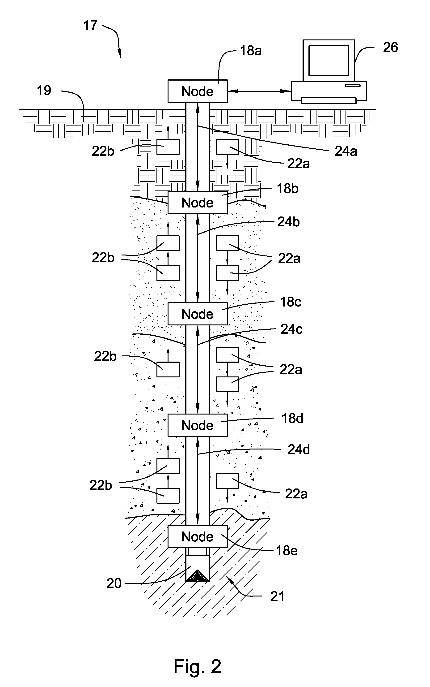
A downhole drilling system is disclosed in one aspect of the present invention as including a drill string and a transmission line integrated into the drill string. Multiple network nodes are installed at selected intervals along the drill string and are adapted to communicate with one another through the transmission line. In order to efficiently allocate the available bandwidth, the network nodes are configured to use any of numerous burst modulation techniques to transmit data.

Description

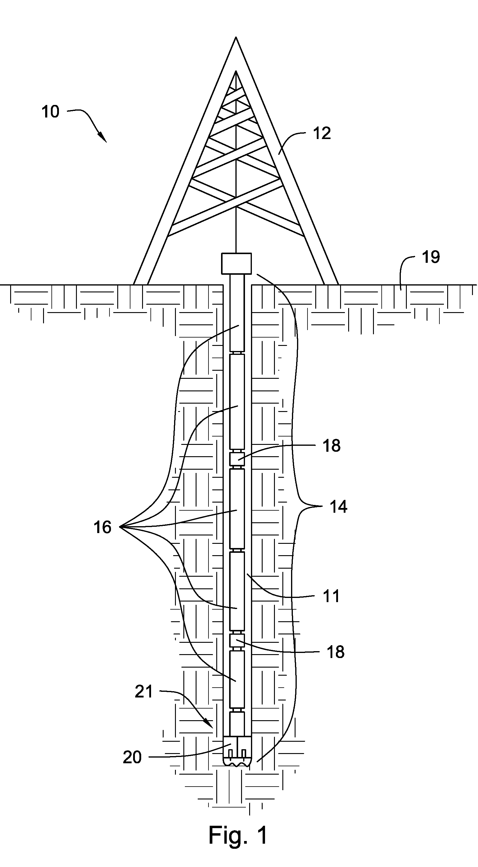
CROSS REFERENCE TO RELATED APPLICATIONS [0001] The present application is a continuation-in-part of copending U.S. patent application Ser. No. 10 / 878,145 filed on Jun. 28, 2004, which is herein incorporated by reference.FEDERAL RESEARCH STATEMENT [0002] This invention was made with government support under Contract No. DE-FC26-01NT41229 awarded by the U.S. Department of Energy. The government has certain rights in the invention.BACKGROUND OF INVENTION [0003] 1. Field of the Invention [0004] This invention relates to oil and gas drilling, and more particularly to apparatus and methods for transmitting data in downhole drilling networks. BACKGROUND OF THE INVENTION [0005] The goal of accessing data from a drill string has been expressed for more than half a century. As exploration and drilling technology has improved, this goal has become more important in the industry for successful oil, gas, and geothermal well exploration and production. For example, to take advantage of the severa...

Claims


Application Information

Patent Timeline
IPC IPC(8): E21B47/12G01V3/00
CPCE21B47/12
Inventor HALLFOX, JOE
Owner INTELLISERV
Learn More