
Balance shaft

Inactive Publication Date: 2005-12-29
HILLSDALE AUTOMOTIVE
View PDF8 Cites 15 Cited by
  • Summary
  • Abstract
  • Description
  • Claims
  • Application Information

AI Technical Summary

Benefits of technology

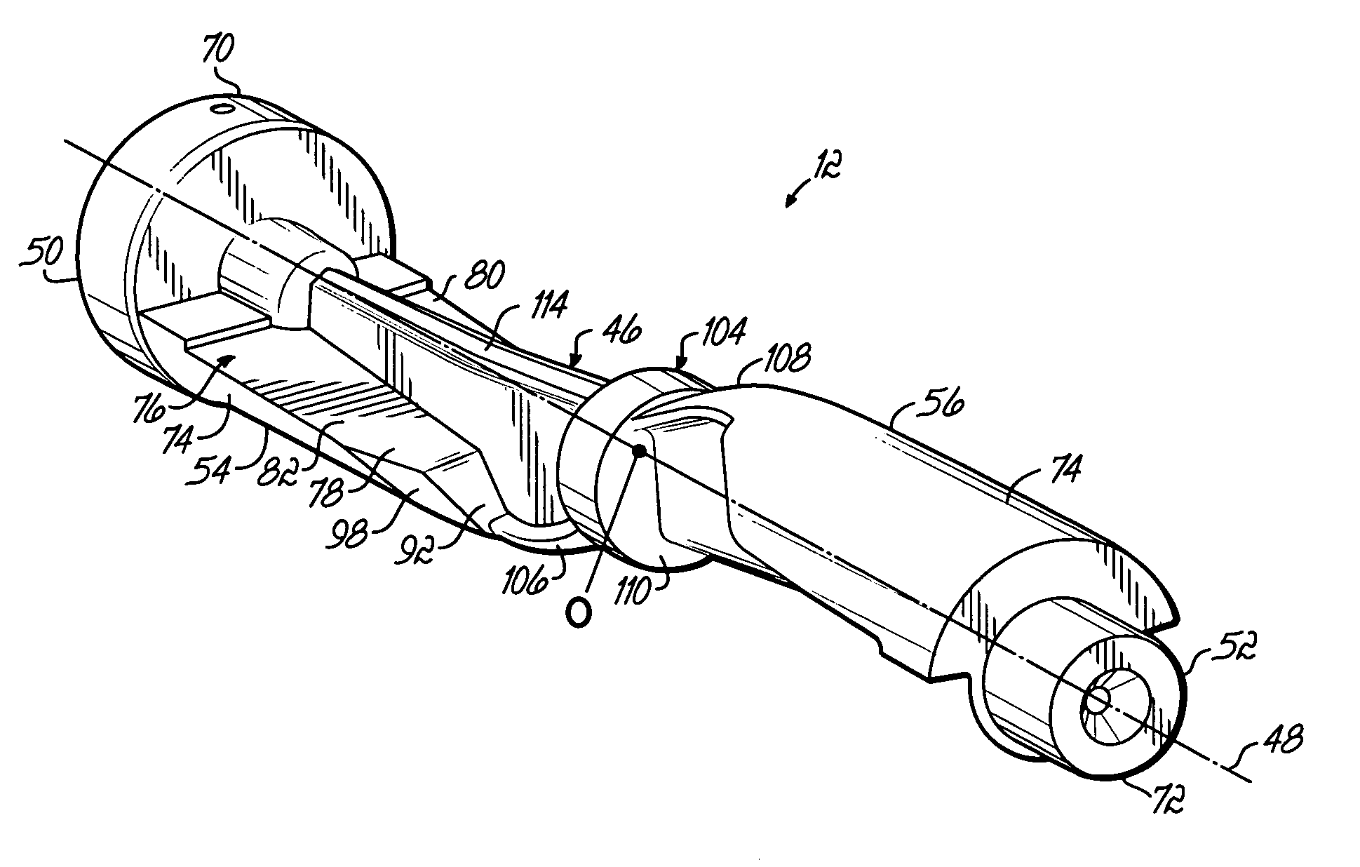
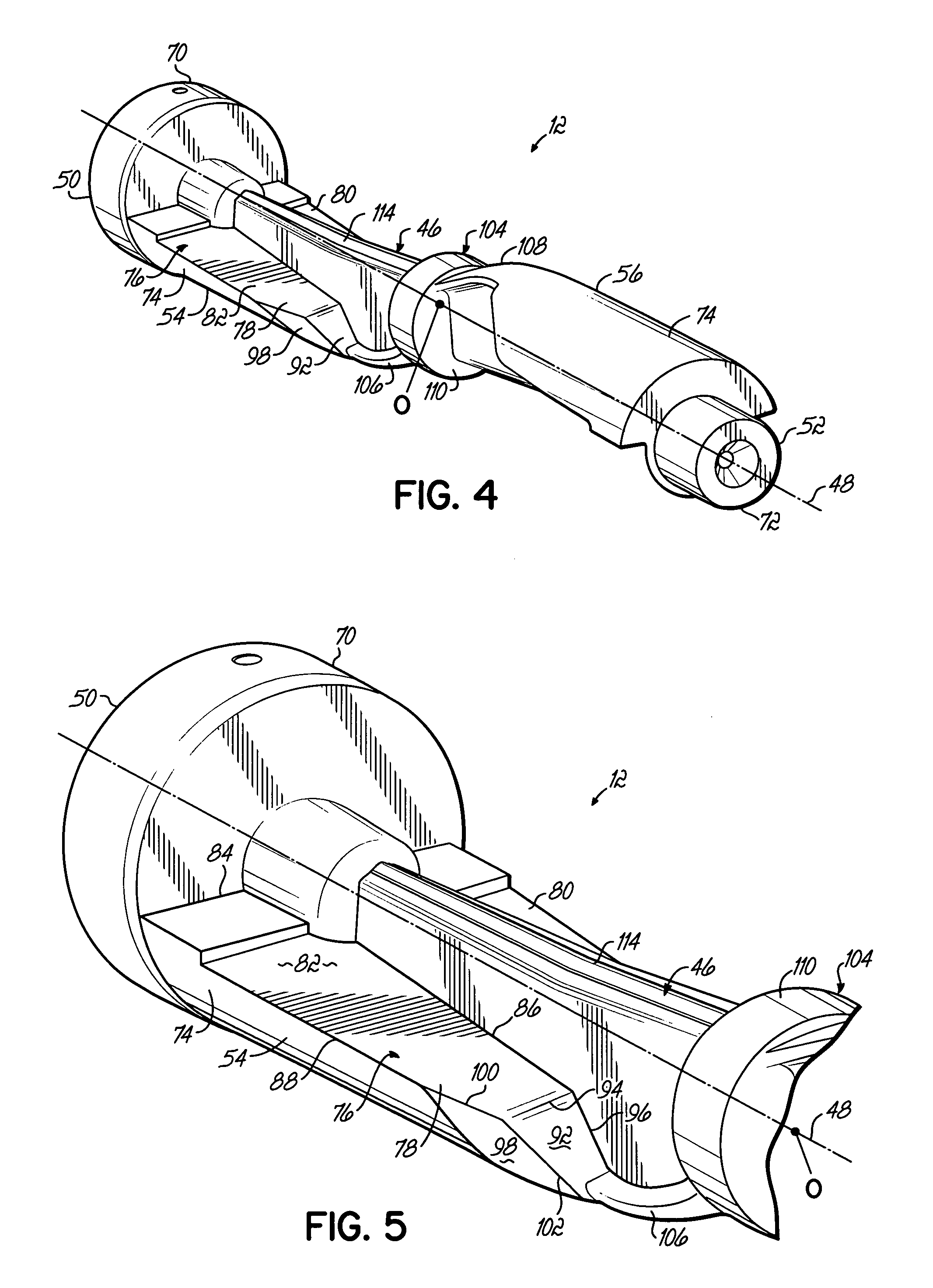
[0008] In one embodiment, the balance shaft includes a first and second bearing surface adjacent the first and second ends respectively. The bearing surfaces support the balance shaft in the engine and allow the shaft to freely rotate about the longitudinal axis. The elongate member includes a connecting portion extending between the first and second counterweights. The connecting portion includes a first flange adjacent the first counterweight and a second flange adjacent the second counterweight such that the cross section of the connecting portion is generally T-shaped. The connecting member may include a central hub so that the first flange extends between the first counterweight and the hub in an arcuate manner and the second flange extends between the second counterweight and the hub also in an arcuate manner. To provide additional strength, the elongate member further includes a first stiffening bead extending along the elongate member opposite the first counterweight and a second stiffening bead extending along the elongate member opposite to the second counterweight.
[0009] By virtue of the foregoing, there is thus provided an improved engine balance shaft having increased strength, a reduction in weight, and thus an overall increase in the strength-to-weight ratio as comparted to current balance shafts.

Problems solved by technology

It is well known, for example, that reciprocating engines have inherent design imbalances that generate undesired effects, such as engine vibration and noise, which contribute to driver / passenger fatigue and irritation as well as engine wear and other structural failures.
It is known that multi-cylinder motor vehicle engines typically generate two types of imbalance forces.
For instance, in-line engine designs, typical of many four-cylinder engines, generally generate both types of imbalance forces while other designs, such as the V-6 design, generate only unbalance moments.

Method used


Image

  • Balance shaft
  • Balance shaft
  • Balance shaft

Examples


Embodiment Construction

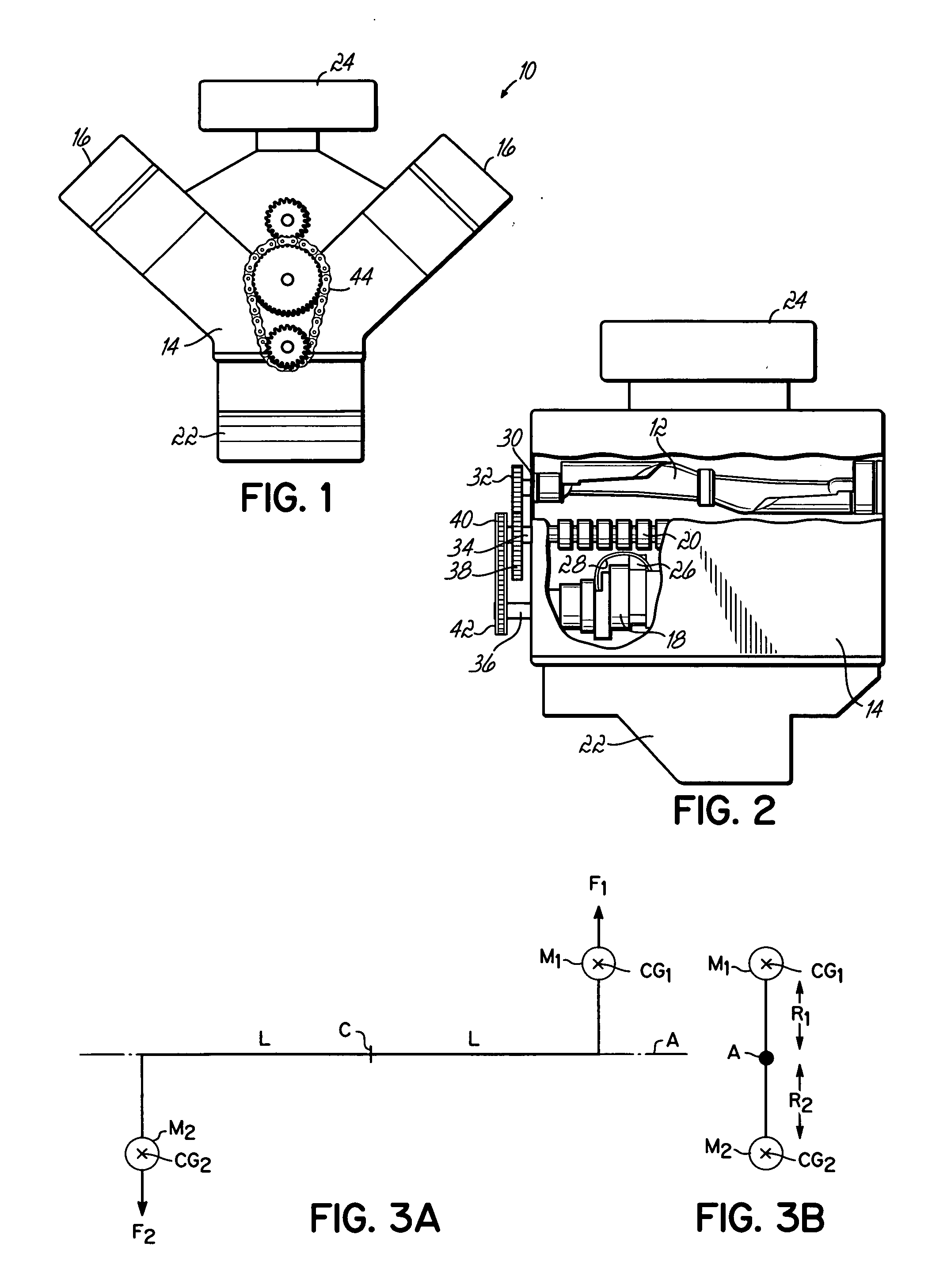
[0019] The balance shaft of the present invention may be used in any type of automobile engine where it is necessary or desirable to reduce or cancel imbalance forces, such as shaking forces and unbalance moments, inherent in the design and operation of the engine. A representative engine in which the present invention may be used is shown in FIGS. 1 and 2 and generally referred to by reference numeral 10.

[0020] The engine 10 is a V-6 engine with two sets of three cylinders spaced 90 degrees apart. These engines, due to their structure and geometry, do not generate any shaking forces but do generate an unbalanced moment which rotates in the opposite direction of the crankshaft. Consequently, this type of engine can significantly benefit from a counter-rotating balance shaft that generates an opposite couple moment. A balance shaft 12 according to the present invention may be incorporated into engine 10 as shown in FIGS. 1 and 2. The balance shaft 12 is configured to generate a coup...


PUM


Abstract

A balance shaft for an engine comprises an elongate member defining a longitudinal axis and having first and second ends. A first counterweight is adjacent the first end and a second counterweight is adjacent the second end and positioned on opposite sides of the longitudinal axis. Each of the counterweights includes a pair of weight portions that are mirror images of each other across the longitudinal axis. Each weight portion includes a first generally planar surface extending in the longitudinal direction, a second generally planar surface inclined with respect to the first surface, and a third generally planar surface inclined with respect to the first and second surfaces. The inclined relation between the three surfaces controls the location of the gravitational center of each counterweight so that when the balance shaft rotates about the longitudinal axis, a couple moment is provided that counteracts the unbalance moment generated by the engine.

Description

FIELD OF THE INVENTION [0001] The invention relates to a balance shaft, and in particular to a balance shaft provided with counterweights for cancelling the unbalance moment produced in reciprocating engines. BACKGROUND OF THE INVENTION [0002] Automotive designers are constantly striving to improve the level of comfort in the automobile for both driver and passengers. It is well known, for example, that reciprocating engines have inherent design imbalances that generate undesired effects, such as engine vibration and noise, which contribute to driver / passenger fatigue and irritation as well as engine wear and other structural failures. As a result, automotive designers and manufactures have for some time utilized balance shafts to reduce or cancel the inherent imbalances generated in the reciprocating engine. [0003] It is known that multi-cylinder motor vehicle engines typically generate two types of imbalance forces. These are generally referred to as shaking forces and unbalance m...

Claims


Application Information

Patent Timeline
IPC IPC(8): F16C3/04F16F15/26
CPCY10T74/2183F16F15/264
Inventor HAWKINS, SCOTTZABONICK, JERRY L.
Owner HILLSDALE AUTOMOTIVE
Learn More