
Standby current generator for an ozonizer

a technology of standby current and ozonizer, which is applied in the field of standby current generator for ozonizer, can solve the problems of oxidation reaction, ozone is composed of three oxygen atoms, and is rather unstable, and achieves the effect of optimizing performance and prolonging li

Inactive Publication Date: 2005-12-22
BIOTEK TECH CORP
View PDF2 Cites 1 Cited by
  • Summary
  • Abstract
  • Description
  • Claims
  • Application Information

AI Technical Summary

Benefits of technology

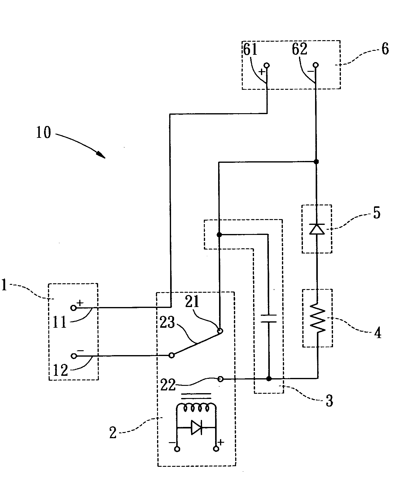
[0005] The present invention is to provide a standby current generator for an ozonizer that resolves the above-mentioned drawbacks. According to one aspect of the present invention, a standby current generator is connected between an ozonizer power source and the ozonizer of a multifunctional oxygenated water machine. When the multifunctional oxygenated water machine is turned off, the standby current generator provides a low standby current to hold the ozonizer at a standby status. Therefore, it can provide the ozonizer with an optimal performance at all time and a longer lifespan.

Problems solved by technology

Ozone is composed of three oxygen atoms and is rather unstable.
Due to this instability, ozone easily reacts with other elements and therefore results in oxidation reaction.
However, since ozone has irritant smell, it may jeopardize human body's health if the added concentration is excessive.
It is known that the conventional ozonizer for the ozonated water generating machine is often damaged by the transient high current when the ozonated water generating machine is turned off.
Besides, since the ozonizer does not standby, the ozonated water can not be generated immediately when next user turns on the ozonated water generating machine again.
Hence, it causes great inconvenience for use.

Method used


Image

  • Standby current generator for an ozonizer
  • Standby current generator for an ozonizer
  • Standby current generator for an ozonizer

Examples


Embodiment Construction

[0011] The present invention will now be described more specifically with reference to the following embodiments. It is to be noted that the following descriptions of preferred embodiments of this invention are presented herein for purpose of illustration and description only; it is not intended to be exhaustive or to be limited to the precise form disclosed.

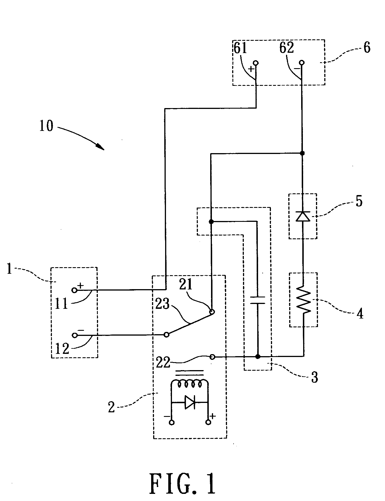
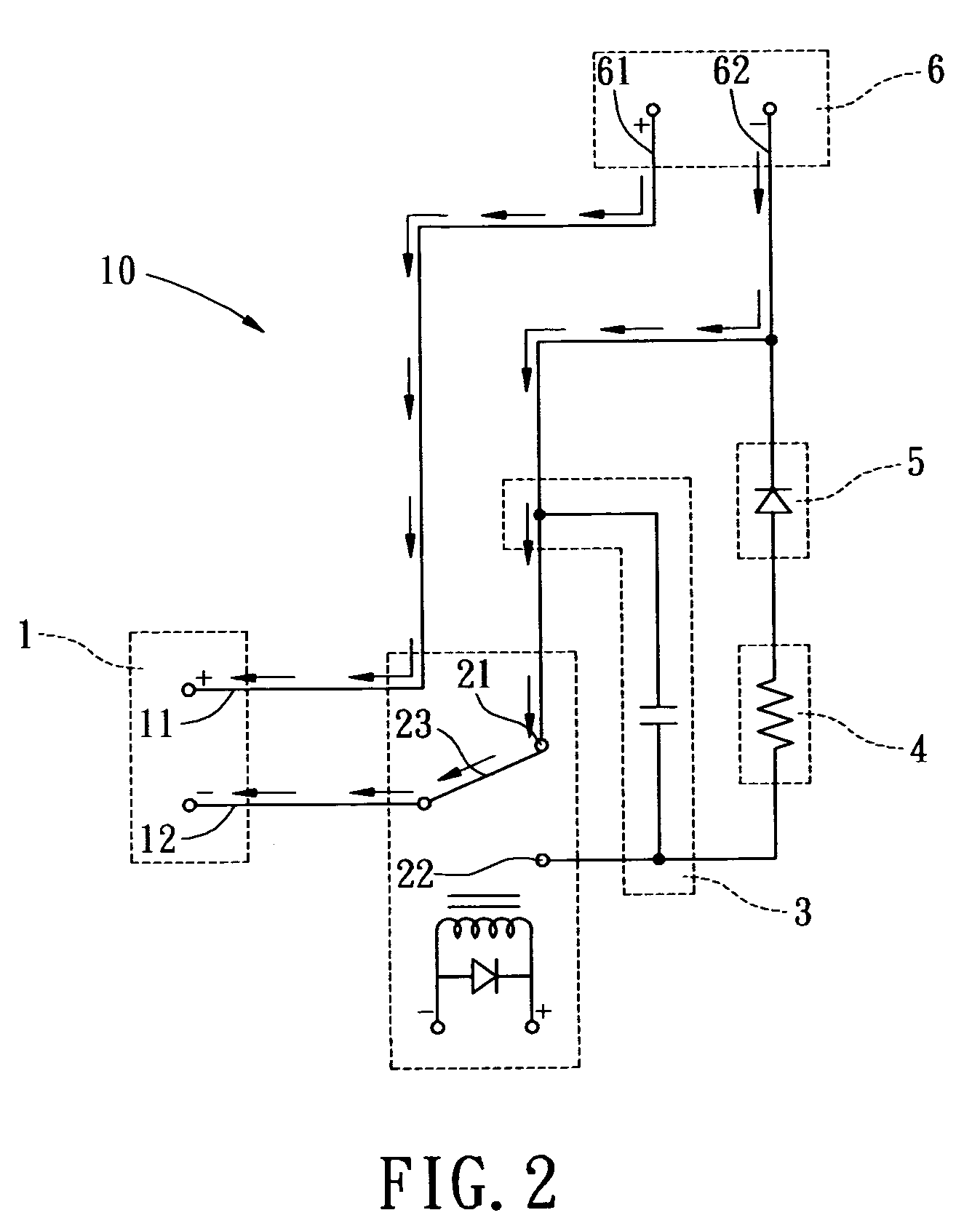
[0012] Please refer to FIG. 1, which is a diagram showing the circuit of the standby current generator according to one preferred embodiment of the present invention. The standby current generator 10 for an ozonizer of a multifunctional oxygenated water machine provided in the present invention is mainly connected between an ozonizer power source and the ozonizer. When the multifunctional oxygenated water machine is turned off, the standby current generator provides a standby current about 100 mA to hold the ozonizer at a standby status so that the ozonizer can have an optimal performance at all time and longer a lifespan.

[001...


PUM

PropertyMeasurementUnit
standby currentaaaaaaaaaa
currentaaaaaaaaaa

Abstract

A standby current generator for an ozonizer is provided. The standby current generator is connected between an ozonizer power source and the ozonizer of a multifunctional oxygenated water machine, which includes a first connecting terminal, a switch unit connected with the first connecting terminal, a first protection unit connected with the switch unit, a second protection unit connected with the switch unit and the first protection unit, a rectifying unit connected with the switch unit and the second protection unit, and a second connecting terminal connected with the rectifying unit and the switch unit. When the multifunctional oxygenated water machine is turned off, the standby current generator provides a low standby current to hold the ozonizer at a standby status. Therefore, the ozoinzer can have an optimal performance at all time and a longer lifespan.

Description

BACKGROUND OF THE INVENTION [0001] The present invention is related to a standby current generator for an ozonizer, and more particularly, to a standby current generator capable of providing a low standby current to the ozonizer of a multifunctional oxygenated water machine when the multifunctional oxygenated water machine is turned off in order to hold the ozonizer at a standby status so that the ozonizer can have an optimal performance at all time and a longer lifespan. [0002] Ozonated water has been gradually learned and accepted by consumers in modern society. As a matter of fact, ozone is very advantageous in people's daily live, especially when it is used for sterilization. The sterilizing effectiveness of ozone is prominently better than that of chlorine used in conventional method. Ozone is composed of three oxygen atoms and is rather unstable. Due to this instability, ozone easily reacts with other elements and therefore results in oxidation reaction. Because of the superio...

Claims


Application Information

Patent Timeline
Patent Type & Authority Applications(United States)
IPC IPC(8): B01J19/08C01B13/11
CPCC01B13/115
Inventor HSU, MAXWELL
Owner BIOTEK TECH CORP
Learn More