Protection circuit and method for protecting a switch from a fault

Active Publication Date: 2005-12-22
DELPHI TECH IP LTD
View PDF6 Cites 2 Cited by
  • Summary
  • Abstract
  • Description
  • Claims
  • Application Information

AI Technical Summary

Benefits of technology

[0006] The present invention is directed to a protection circuit and method for protecting a switch from a fault. The method senses a low-side load current through the switch, which includes a first terminal, a second terminal and a control terminal. The first terminal is connected to a low-side of a load and the second terminal is connected to ground. The switch provides a conductive path between the first and second

Problems solved by technology

Over-current and short circuit protection circuits for protecting drive outputs, e.g., low-side drive outputs, are generally expensive and have a relatively wide tolerance.
Unfortunately, protection circuits that have a relatively wide tolerance may allow for excessive power dissipation in the output driver that they are to protect.
However, these techniques tend to be relatively expensive and may not provide acceptable accuracy to prevent an output driver from experiencing excessive power dissipation.
Unfortunately, wide variations in the base-to-emitter voltage Vbe of the transistor Q2 with temperature causes a relatively wide variation in the current conducted by the transistor Q3.
This leads to a power dissipation for the transistor Q3 of between 30 and 50 Watts.
Additionally, in the event that the power dissipation of the transistor Q3 reaches too high of a level, the transistor Q3 may fail.

Method used


Image

  • Protection circuit and method for protecting a switch from a fault
  • Protection circuit and method for protecting a switch from a fault

Examples


Embodiment Construction

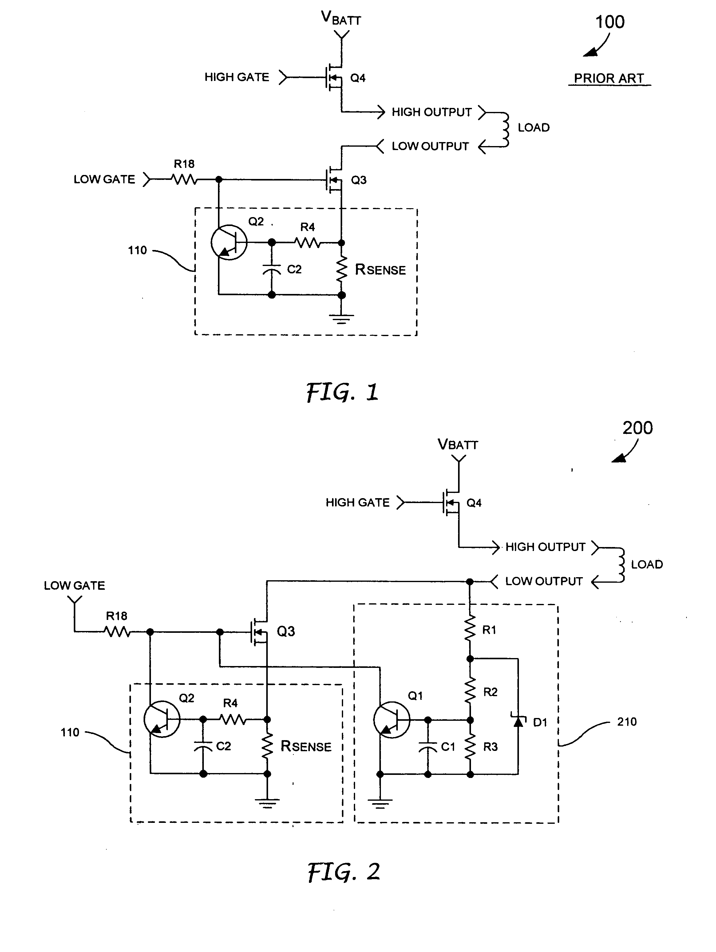
[0015] In a typical high-side driver configuration, a low-side driver is gated on by an external control device and the high-side driver is pulse width modulated to provide a current to the load. According to the present invention, a sensing circuit 210 is provided that triggers when a voltage at a low-side of the load exceeds a desired value. When the circuit 210 triggers, transistor Q1 turns on and pulls the gate of the transistor Q3 to ground. As previously discussed, the protection circuit 110 includes a transistor Q2, which is turned on by an overcurrent fault. When the transistor Q2 is turned on, the transistor Q2 pulls the gate of the transistor Q3 toward ground and, thus, causes the transistor Q3 to operate in a linear mode. When Q3 is operating in a linear mode, the voltage at the drain of the transistor Q3, or the low-side of the load, rises. As the voltage at the low-side of the load rises, the current is conducted by a resistive voltage divider, which includes resistors ...


PUM


Abstract

A protection circuit for protecting a switch from a fault includes a first sensing circuit and a second sensing circuit. The first sensing circuit senses a low-side load current through a switch that includes a first terminal, a second terminal and a control terminal. The first terminal is connected to a low-side of the load and the second terminal is connected to ground. The switch provides a conductive path between the first and second terminals responsive to a control signal provided on the control terminal. The first sensing circuit acts to reduce a magnitude of the control signal to limit the low-side load current, carried by the switch, when the low-side load current exceeds a first predetermined value. The second sensing circuit senses a voltage at the low-side of the load and interrupts the low-side load current, when the voltage at the low-side of the load exceeds a second predetermined value.

Description

TECHNICAL FIELD [0001] The present invention is generally directed to a protection circuit and, more specifically, a protection circuit for protecting a switch from a fault. BACKGROUND OF THE INVENTION [0002] Over-current and short circuit protection circuits for protecting drive outputs, e.g., low-side drive outputs, are generally expensive and have a relatively wide tolerance. Unfortunately, protection circuits that have a relatively wide tolerance may allow for excessive power dissipation in the output driver that they are to protect. In general, automotive applications require protection of each connector pin of an assembly from short-to-battery faults and short-to-ground faults. A variety of techniques have been utilized to protect various input / output (IO) pins of an electronic device from faults. These techniques have included implementing self-protected output drivers, operational amplifier circuits and individual transistor circuits. However, these techniques tend to be rel...

Claims


Application Information

Patent Timeline
IPC IPC(8): H02H3/20H03K17/082
CPCH03K17/0822
Inventor PRITCHETT, THOMAS E.SULLIVAN, DALE R.
Owner DELPHI TECH IP LTD
Why Eureka
Try Eureka