
Double-sided silent chain

a double-sided, silent technology, applied in the direction of driving chains, belts/chains/gearrings, chain elements, etc., can solve the problems of reduced rotational fatigue strength of the chain, reduced strength of the outermost link plate, and easy wear of the teeth of the link plate adjacent the guide plate, so as to improve prevent the deformation of the link plate. , the effect of improving the strength of the central portion

Active Publication Date: 2005-12-15
TSUBAKIMOTO CHAIN CO
View PDF14 Cites 13 Cited by
  • Summary
  • Abstract
  • Description
  • Claims
  • Application Information

AI Technical Summary

Benefits of technology

[0015] The invention solves the problems encountered in conventional double-sided silent chains by improving the strength of the central portions of the outermost link plates. The improvement in strength of the central portions of the outermost link plates prevents deformation of the link plates as a result of collision of their teeth with sprocket teeth at the start of engagement with a sprocket, prevents cracks from occurring at the tooth gap bottoms, and improves the rotational fatigue strength of the chain. Further improvements can be realized when the heights of the backs of the outermost link plates and the heights of the backs of the adjacent outer link plates are both greater than the heights of the backs of the inner link plates.
[0016] Preferably, the outermost link plates and the adjacent outer link plates are both of the outer tooth contact and outer tooth seating type. In this case, at the start of engagement between the chain and the sprocket, the outer tooth surfaces come into contact with tooth surfaces of sprocket teeth, and the outer tooth surfaces of the link teeth also contact the sprocket teeth when the chain is seated on the sprocket. Consequently, the inner tooth surfaces do not come into contact with the sprocket teeth, and as a result, the load applied to the central portion of the link plates is decreased, the fatigue strengths of these link plates can be further improved, and the rotational fatigue strength of the chain is also further improved.

Problems solved by technology

This weakness, in the outermost link plates, manifests itself in the formation of cracks near the tooth gap bottom, a progressive decrease in the strength of the outermost link plates, and a reduction in rotational fatigue strength of the chain.
However, with this approach, the teeth of the link plates adjacent the guide plates are easily worn.
However increasing the width of a link plate, or adding link plates, results in a disadvantageous increase in the width of the chain.

Method used


Image

  • Double-sided silent chain
  • Double-sided silent chain
  • Double-sided silent chain

Examples

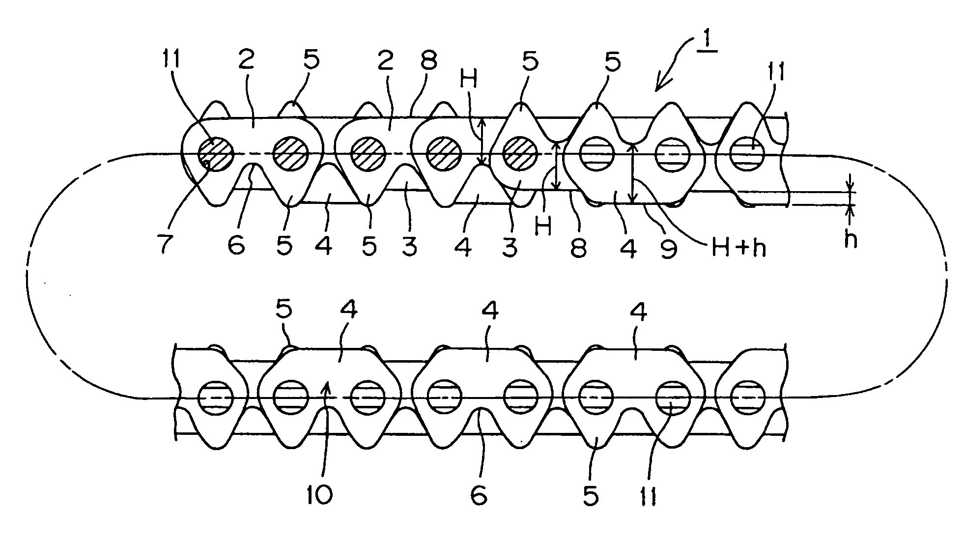
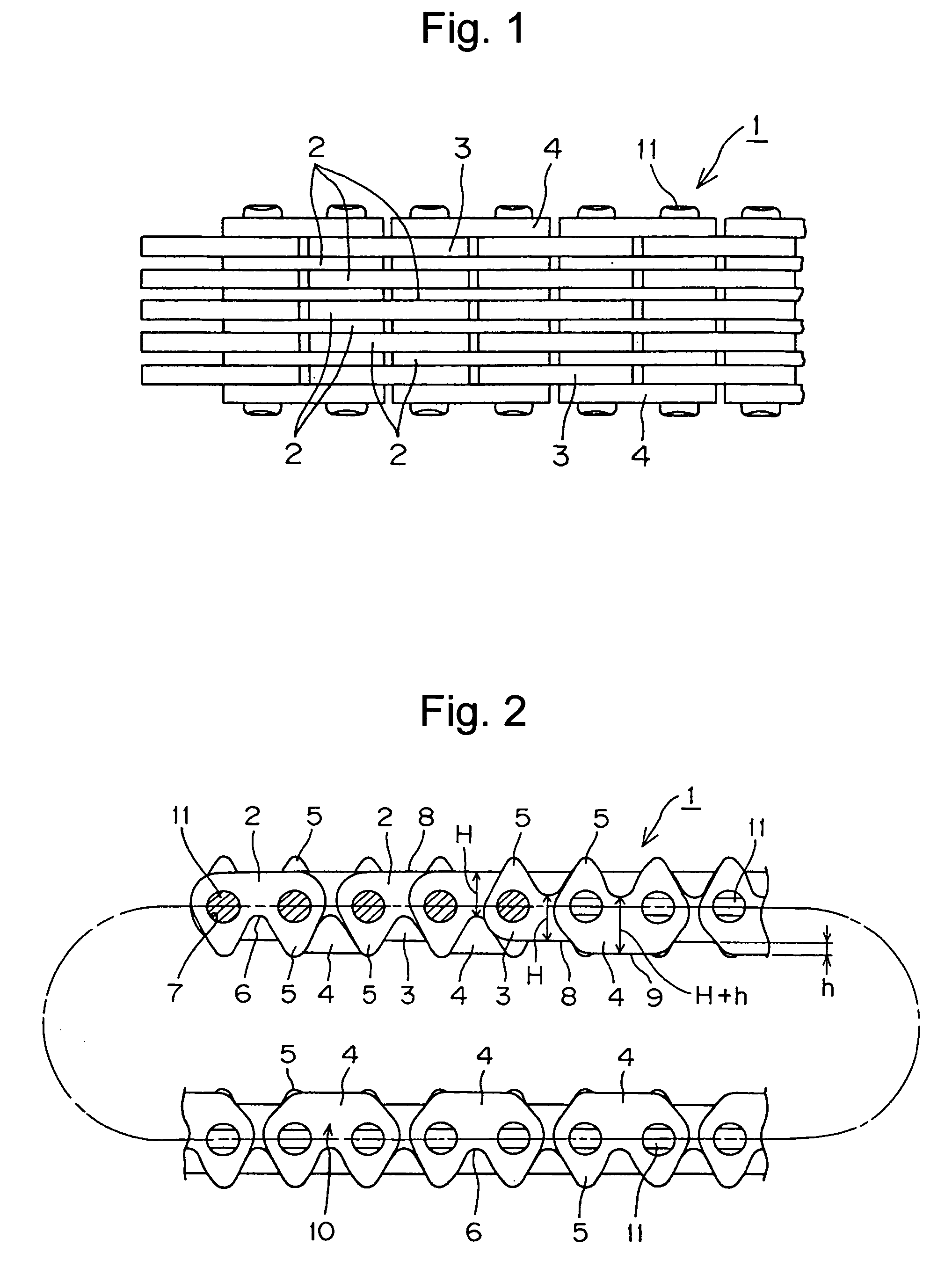

first embodiment

[0030] the invention will be described with reference to FIGS. 1, 2, 5 and 6. The link plates of the chain are interleaved, alternately displaced longitudinally, and connected in an endless loop by connecting pins. The link plates are also disposed so that teeth protrude toward both the front and back sides of the chain.

[0031] In the first embodiment, the inner link plates 2, and the outer link plates 3, which are adjacent, but inward with respect to the outermost link plates 4, are of the same size and shape. Each of these link plates has a pair of pin holes 7, a pair of protruding teeth 5, and a flat back surface 8 facing in the direction opposite to the direction in which the teeth 5 protrude.

[0032] Each of the outermost link plates 4, which are disposed along both sides of the chain, has a pair of teeth 5, a pair of pin holes 7, and a flat back surface 9. However, the back surfaces 9 of these outermost link plates are higher than the back surfaces 8 of link plates 2 and 3. That...

second embodiment

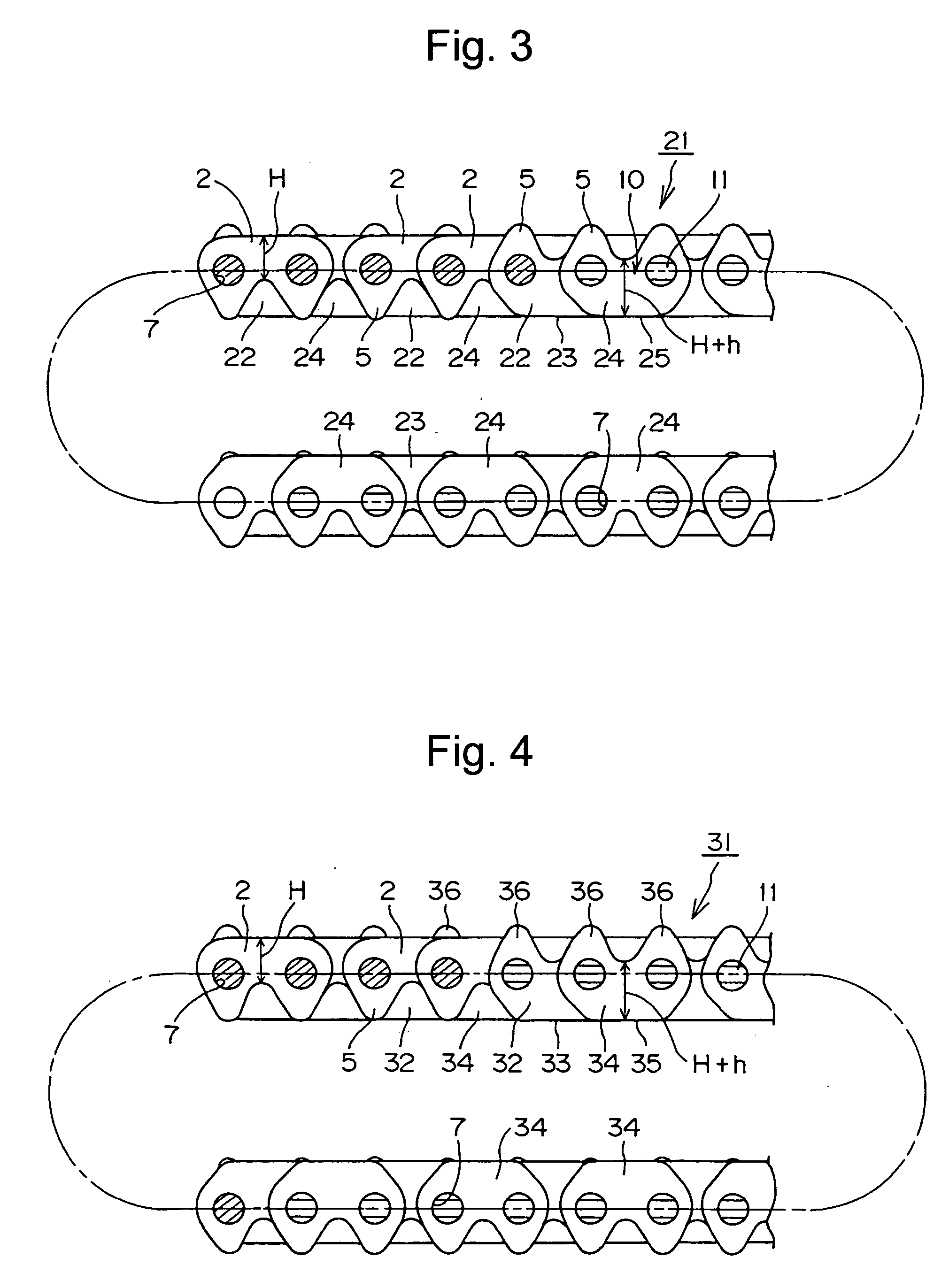
[0043] In the invention, shown in FIG. 3, the double-sided silent chain 21 differs from the embodiment of FIGS. 1 and 2 only in that the heights of the backs of the outer link plates adjacent the outermost link plates, as well as the backs of the outermost link plate, are higher than the backs of the inner link plates. Otherwise the structure of the chain 21 is the same as that of the chain shown in FIGS. 1 and 2, and identical parts are denoted by the same reference numerals.

[0044] The heights of the backs of the inner link plates 2 are the same as those of link plates 2 in FIG. 2, and, as in the case of the link plates 2 in FIG. 2, the link plates 2 in FIG. 3 are of the inner tooth surface contact and outer tooth seating type. The outermost link plates 24 and their adjacent outer link plates 22 have the same size and the same shape, each having a pair of teeth 5 and a pair of pin holes 7. These link plates 24 and 22, respectively, have flat back surfaces 25 and 23 facing the direc...

third embodiment

[0048] In the invention, as depicted in FIG. 4, the double-sided silent-chain 31 also differs from the embodiment of FIGS. 1 and 2 in that the heights of the backs of the outer link plates adjacent the outermost link plates, as well as the backs of the outermost link plate, are higher than the backs of the inner link plates. Otherwise the configuration of the chain 21 is the same as that of the chain shown in FIGS. 1 and 2, and identical parts are denoted by the same reference numerals.

[0049] The heights of the backs of the inner link plates 2 are the same as those of link plates 2 in FIG. 2, and, as in the case of the link plates 2 in FIG. 2, the link plates 2 in FIG. 3 are of the inner tooth surface contact and outer tooth seating type. The outermost link plates 34 and their adjacent outer link plates 32 have the same size and the same shape, each having a pair of teeth 36 and a pair of pin holes 7. These link plates 34 and 32, respectively, have flat back surfaces 35 and 33 facin...


PUM


Abstract

In a double-sided silent chain, the backs of the outermost link plates, which have their teeth protruding in one direction, are higher than the backs of the inner link plates, which have their teeth protruding in the opposite direction. The backs of the outer link plates adjacent the outermost link plates may also be higher than the backs of the inner link plates, and are preferably equal to the heights of the backs of the outermost link plates. The outermost link plates and their adjacent outer link plates are preferably of the outer tooth contact / outer tooth seating type.

Description

FIELD OF THE INVENTION [0001] This invention relates to improvements in a double-sided silent chain, that is, a silent chain formed into an endless loop and adapted for driving engagement with two or more sprockets inside the loop and one or more sprockets outside the loop. Such a chain is composed of a plurality of link plates, each having a pair of pin holes, a pair of link teeth projecting in a first direction, and a flat back surface facing in the opposite direction. The link plates are interleaved, alternately displaced longitudinally, and connected to one another by connecting pins as in the case of a conventional silent chain. In a double-sided chain, however, the link plates are arranged so that the teeth of one set of link plates protrude toward the inside of the loop, and the teeth of another set of link plates protrude toward the outside of the loop. BACKGROUND OF THE INVENTION [0002] Japanese Laid-open Patent Publication No. Hei. 11-166600, U.S. Pat. No. 6,142,902, and J...

Claims


Application Information

Patent Timeline
Patent Type & Authority Applications(United States)
IPC IPC(8): F16G13/02F16G13/04
CPCF16G13/04
Inventor OGO, TOSHITAKASATO, TOSHIFUMI
Owner TSUBAKIMOTO CHAIN CO
Learn More