
Measuring device and methods for use therewith

a measuring device and measurement method technology, applied in the field of electrochemical interface apparatus, can solve problems such as circuit failure and inability to yield signals

Inactive Publication Date: 2005-12-15
AGAMATRIX INC
View PDF9 Cites 97 Cited by
  • Summary
  • Abstract
  • Description
  • Claims
  • Application Information

AI Technical Summary

Benefits of technology

[0015] The ability to switch at will between amperometric measurements and potentiometric measurements provides great flexibility in performing analyses of unknowns. The various potential benefits of this approach are discussed in some detail in co-pending U.S. application Ser. No. 10 / 924,510, filed Aug. 23, 2004 and incorporated herein by reference for all purposes. Measurement approaches are discussed in some detail in U.S. appl. No. ______ (docket 15), filed (when), and in U.S. appl. No. ______ (docket 16), filed (when), each of which is incorporated herein by reference for all purposes.

Problems solved by technology

Stating the same point in different terms, this circuit does not and cannot yield a signal that is independent of concentration of the analyte.

Method used


Image

  • Measuring device and methods for use therewith
  • Measuring device and methods for use therewith
  • Measuring device and methods for use therewith

Examples


Embodiment Construction

[0032] Variations upon the topology will now be described.

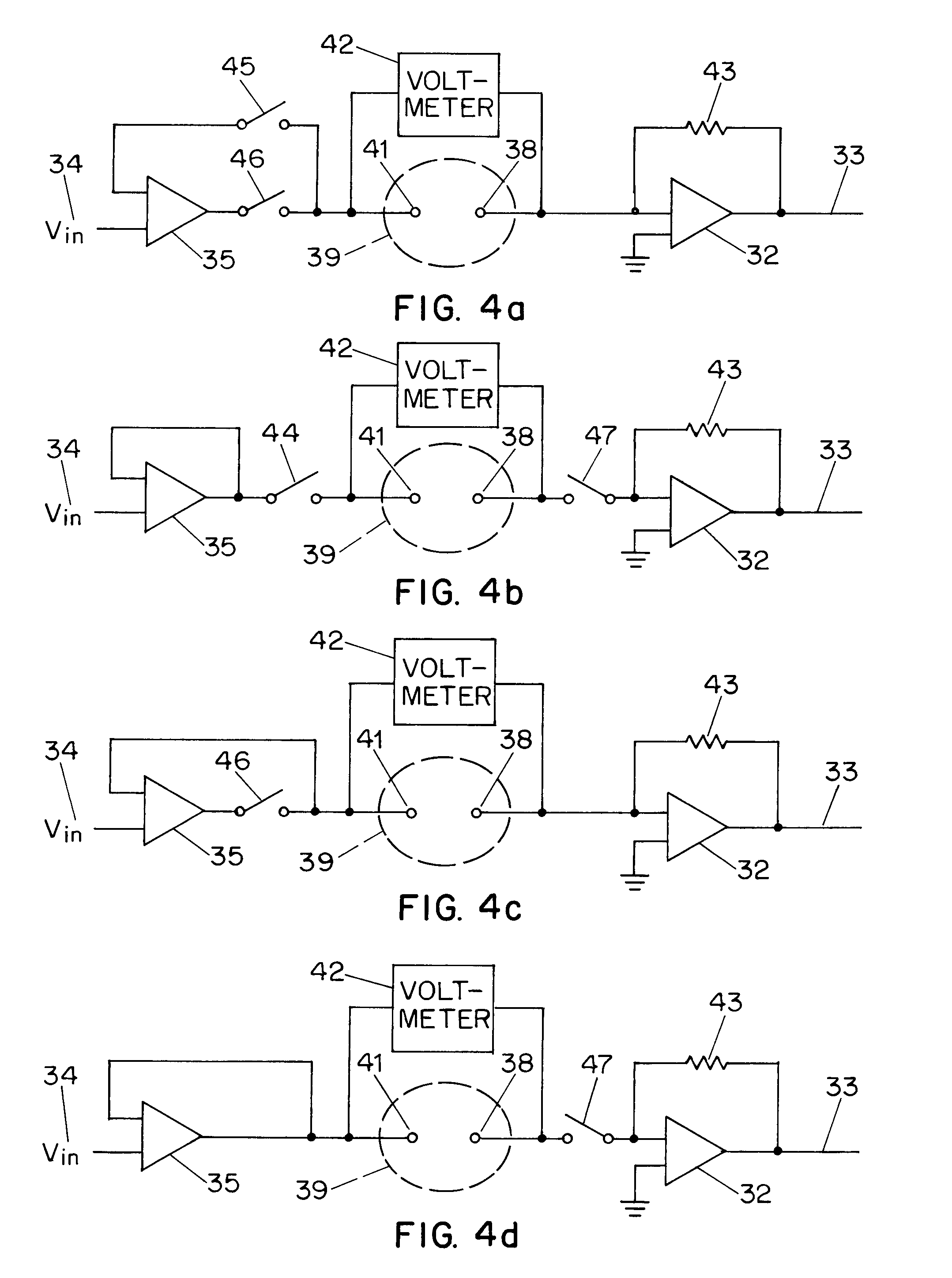
[0033]FIGS. 4a and 4b show embodiments in which two switches are used rather than the single switch of FIG. 3. In each embodiment, two switches are opened to isolate the cell for purposes of voltage measurement by means of voltmeter 42.

[0034] In FIG. 4a, switches 45, 46 are opened to isolate the two-electrode cell 39 from the output of amplifier 35 and from the feedback path to the inverting input of amplifier 35.

[0035] In FIG. 4b, switches 44, 47 are opened to isolate the two-electrode cell 39 at both the electrode 41 and the electrode 38.

[0036]FIGS. 4c and 4d show embodiments in which one switch is used to effect the isolation. In each embodiment, a single switch is opened to isolate the cell for purposes of voltage measurement by means of voltmeter 42.

[0037] In FIG. 4c, switch 46 is opened to isolate the two-electrode cell 39 from the output of amplifier 35.

[0038] In FIG. 4d, switch 47 is opened to isolate the two-el...


PUM

PropertyMeasurementUnit
electrical connectionaaaaaaaaaa
electricalaaaaaaaaaa
transparentaaaaaaaaaa

Abstract

The ability to switch at will between amperometric measurements and potentiometric measurements provides great flexibility in performing analyses of unknowns. Apparatus and methods can provide such switching to collect data from an electrochemical cell. The cell may contain a reagent disposed to measure glucose in human blood.

Description

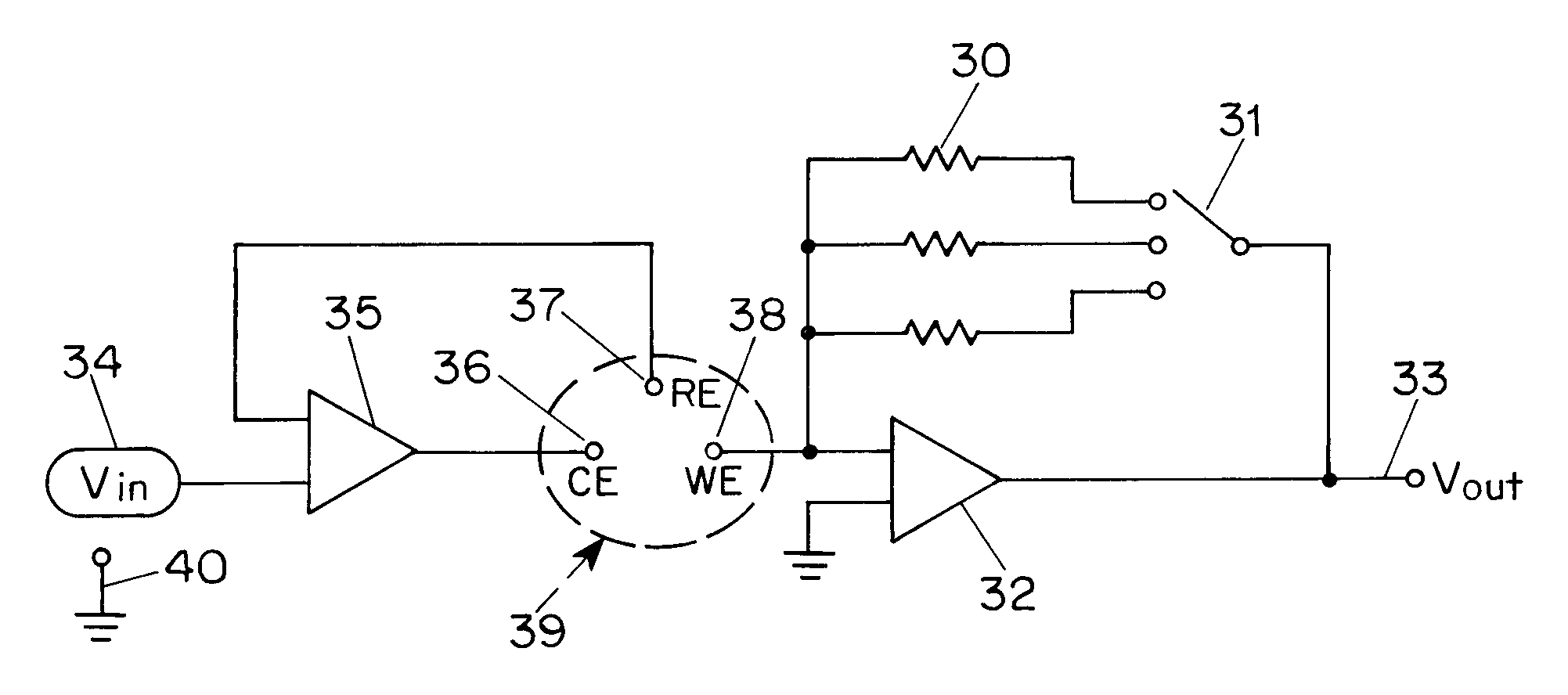
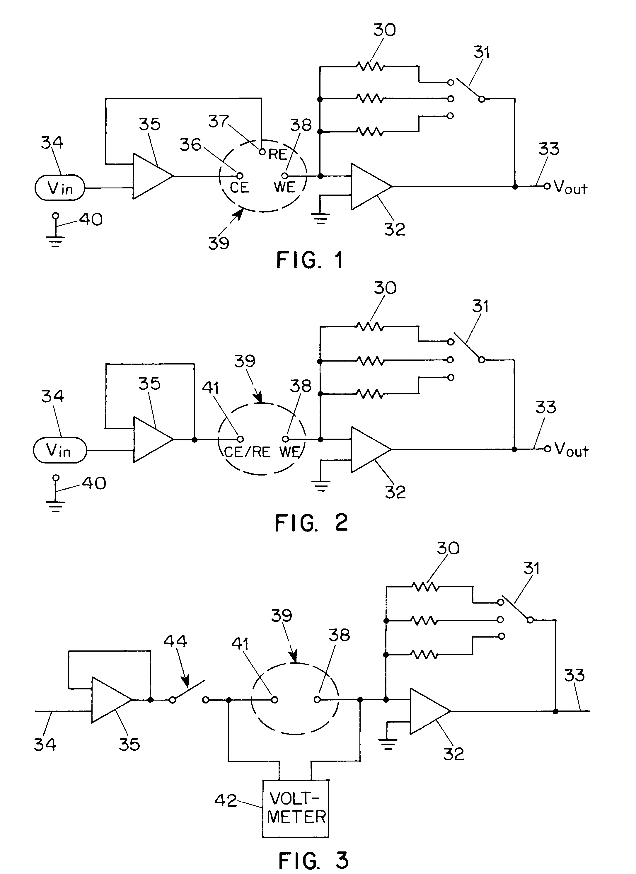
CROSS-REFERENCE TO RELATED APPLICATIONS [0001] This application claims priority from U.S. application No. 60 / 521,592 filed May 30, 2004, and from U.S. application No. 60 / 594,285 filed Mar. 25, 2005, each of which is incorporated herein by reference for all purposes.BACKGROUND [0002] Electrochemical reactions may be used to measure quantities and concentrations in solutions. [0003]FIG. 1 is a schematic diagram of an electrochemical interface apparatus, also known as a potentiostat, for a standard three-electrode configuration. Electrochemical cell 39 has a reference electrode 37, a counter electrode 36, and a working electrode 38. The cell 39 contains a substance being analyzed as well as a reagent selected for its utility. The reagent forms part of an electrochemical reaction. It will be appreciated that there are other circuits that can accomplish the functions described here, and that this is only one embodiment thereof. [0004] A voltage is applied to the cell at 36, based upon a ...

Claims


Application Information

Patent Timeline
Patent Type & Authority Applications(United States)
IPC IPC(8): G01N27/26G11C7/00
CPCG01N33/48785
Inventor HARDING, IANIYENGAR, SRIDHAR G.WEI, BAOGUOVU, SONNYHUANG, EILEENFLAHERTY, JOSEPHDIAMOND, STEVENFOREST, MARTIN
Owner AGAMATRIX INC
Learn More