
Method and drum for molding tire

Active Publication Date: 2005-12-15
BRIDGESTONE CORP
View PDF6 Cites 9 Cited by
  • Summary
  • Abstract
  • Description
  • Claims
  • Application Information

AI Technical Summary

Benefits of technology

[0007] Here, when the end portion of the carcass band is turned, the carcass band is pushed onto the rigid support members from an outside in the axial direction together with the bead filler and the like, and the pushing force is surely and sufficiently supported by the rigid support members having a rigidity fairly higher than that of a rubber bladder without a draft deformation or the like, so that the pressing force of the carcass band to the bead filler can be largely enhanced over the whole of the arranging region of the bead filler as compared with the conventional technique, and hence the residual air therebetween can be pushed out and removed more effectively.
[0021] According to this construction, the force in the diameter-expansion direction can be applied to the carcass band and the bead core accompanied with the supply of an internal pressure to the outer fold bladder in the turning of the carcass band to enhance the pressing force of the carcass band to the bead core, and hence the residual air therebetween can be effectively removed and the restraint force to the pulling-out of the cords can be enhanced.

Problems solved by technology

According to such a conventional technique, however, the interior bladder is made from a rubber membrane body provided with a reinforcing layer and is relatively low in the rigidity even at the diameter-expanded state, so that the pressing force of the carcass to the bead filler can not be sufficiently enhanced, and hence there is still a fear of retaining air in the bead portion.
As a result, there are problems that the uniformity of the product tire may not be held at a good level and in extreme cases, the residual air causes the lowering of the durability in the bead portion.

Method used


Image

  • Method and drum for molding tire
  • Method and drum for molding tire
  • Method and drum for molding tire

Examples


Embodiment Construction

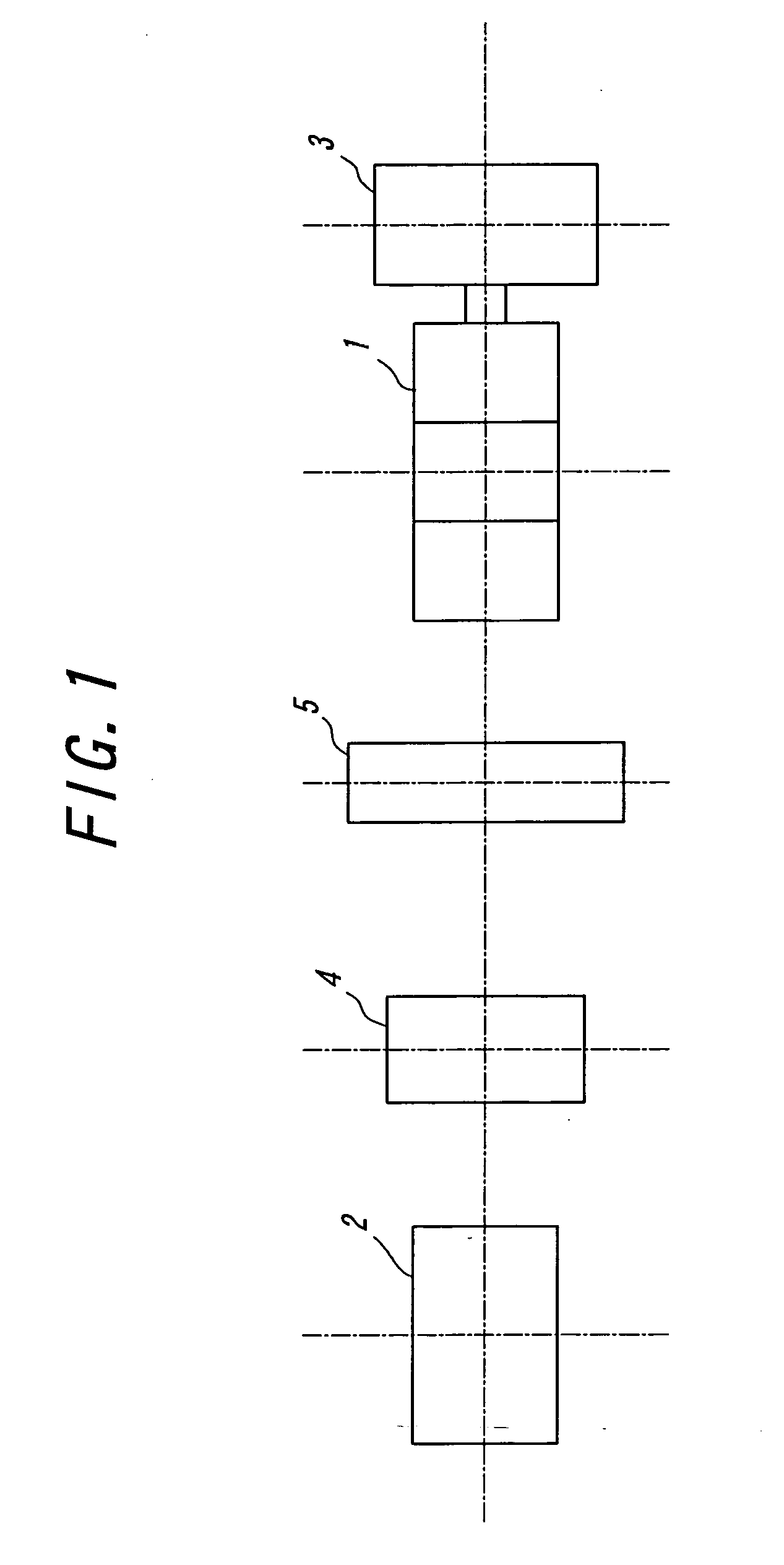
[0028] In FIG. 1, numeral 1 is a tire building drum aiming at the invention, and numeral 2 a band shaping drum located at a left end of the figure and forming a green case to be transferred to the building drum 1, and numeral 3 a belt-tread shaping drum located adjacent to a right side of the building drum 1 in the figure. The band shaping drum 2 is devoted to the formation of a green case composed mainly of a carcass band, bead cores and bead fillers, and the belt-tread shaping drum 3 is devoted to the formation of a belt-tread band composed mainly of a belt and a tread.

[0029] Also, numeral 4 is means for holding and transferring the green case. The green case holding and transferring means 4 functions to transfer and deliver the green case (not shown) formed on the band shaping drum 2 to the building drum 4.

[0030] Numeral 5 is means for holding and transferring the belt-tread band. The belt-tread band holding and transferring means 5 functions to transfer the belt-tread band (no...


PUM

PropertyMeasurementUnit
Diameteraaaaaaaaaa
Lengthaaaaaaaaaa
Widthaaaaaaaaaa

Abstract

There are provided a method and a drum for building a tire in which residual air can be effectively removed by enhancing a pressing force of a carcass band to a bead filler in the turning of the carcass band around a bead core, wherein a cylindrical green case is arranged on an outer peripheral side of a building drum, and a central portion of the green case is expansion-deformed in a radial direction while approaching both the bead cores to each other under a restraint of the bead core through the building drum, and the green case is pressed onto an inner peripheral face of a belt-tread band, and thereafter both the end portions of the carcass band are turned around the bead cores so that the carcass band is pushed onto rigid support members disposed at an inner peripheral side of the carcass band together with the bead cores and bead fillers.

Description

TECHNICAL FIELD [0001] This invention relates to a method of building a tire and a tire building drum used therefor, and particularly proposes a technique for effectively preventing residual air between a carcass and a bead filler. BACKGROUND ART [0002] In the building of the tire, a previously shaped green case composed mainly of a cylindrical carcass band, annular bead cores and bead fillers is arranged on an outer peripheral side of a tire building drum, and a central portion of the green case is expansion-deformed under an action of a building bladder disposed in the tire building drum while approaching both the bead cores to each other under a restraint of the bead cores by this building drum, and then the central portion of the green case is pressed onto an inner peripheral face of a belt-tread band composed mainly of a belt and a tread previously disposed on an outer peripheral side of the drum, and thereafter each end portion of the carcass band is turned around the bead cor...

Claims


Application Information

Patent Timeline
IPC IPC(8): B29D30/24B29D30/36
CPCB29D30/246B29D30/36B29D2030/3228B29D2030/3235
Inventor TOKUNAGA, TOSHIO
Owner BRIDGESTONE CORP
Learn More