
Modular intramedullary nail

a module and intramedullary technology, applied in the field of modules, can solve the problems of insufficient telescopic attachment, large number of nails and instruments, and difficulty for surgeons and nurses to master a great, and achieve the effect of improving vascularization and biomechanical stability

Inactive Publication Date: 2005-12-08
STRYKER EURO OPERATIONS HLDG LLC
View PDF19 Cites 38 Cited by
  • Summary
  • Abstract
  • Description
  • Claims
  • Application Information

AI Technical Summary

Benefits of technology

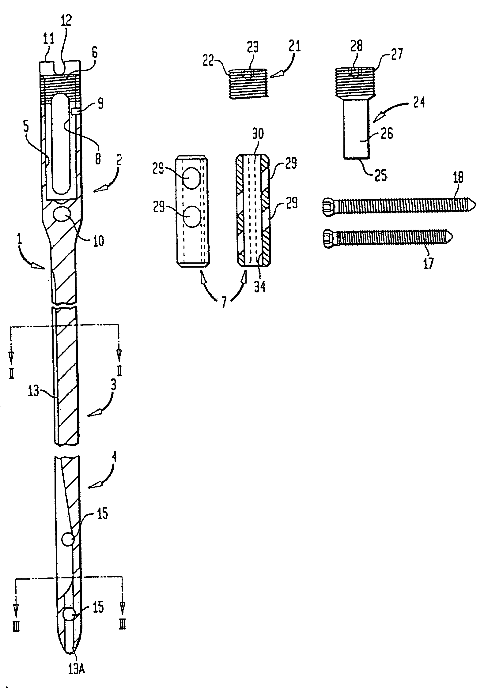
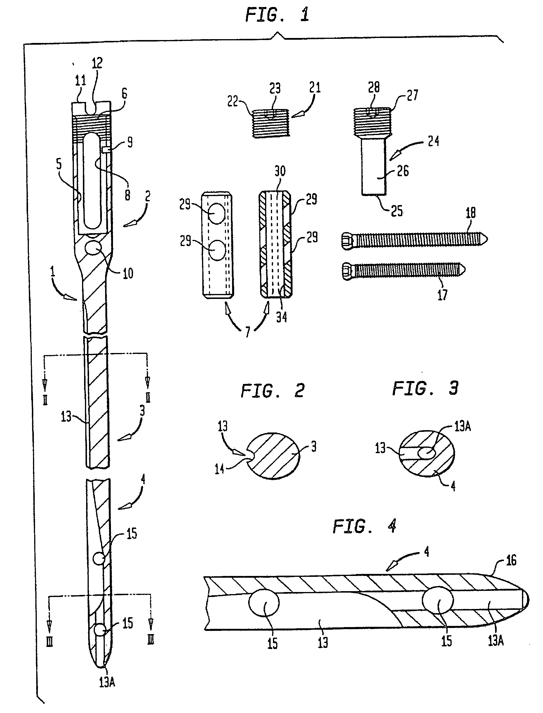
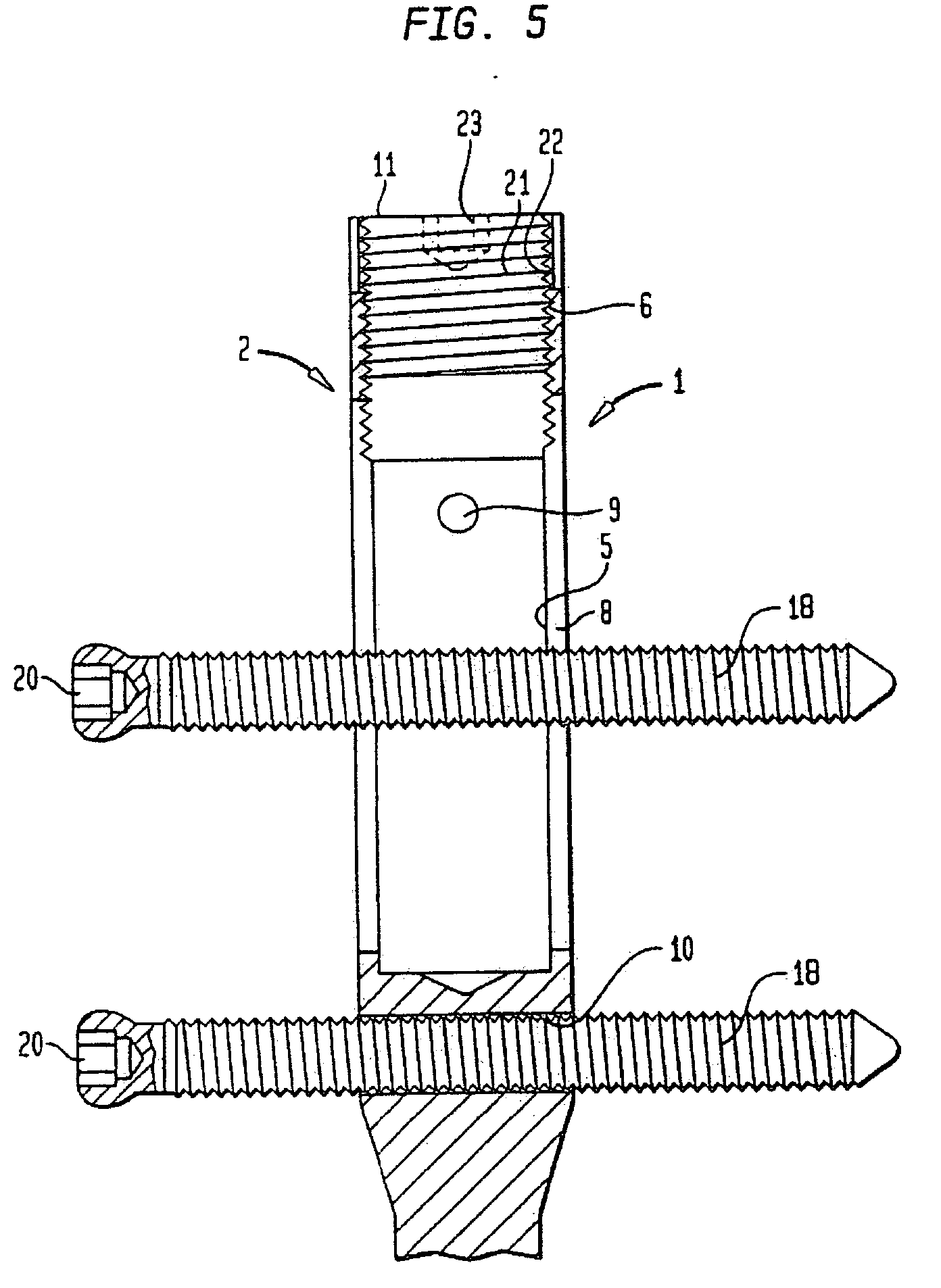
[0006] On the background of this prior art, it is the object of the present invention to provide a modular intramedullary nail and a relating method where the above-mentioned drawbacks are eliminated and which has an increased biomechanical stability and ensures a better vascularization. This object is attained by an intramedullary nail wherein the proximal portion comprises a longitudinal bore extending over the longitudinal extension of said slot in the distal direction and an insert which is intended to be inserted in said longitudinal bore, said insert comprising at least one guiding bore which is intended to receive fixing elements.

Problems solved by technology

This leads to an expensive storage of a large number of nails and instruments.
Furthermore, it is increasingly difficult for the surgeon and the nurses to master a great number of different implant systems in such a manner that an optimum treatment of fractures is ensured.
However, such a telescopic attachment is not optimal with respect to biomechanical aspects, which must be considered as essential on account of the great loads at the proximal femur, and furthermore, the proximal portion of the nail is additionally thickened by the attached sleeve, thus resulting in negative effects with respect to the vascularization of the neck area of the femur head.
This device is designed for a particular type of fracture and does not permit the reduction of required intramedullary nails.

Method used


Image

  • Modular intramedullary nail
  • Modular intramedullary nail
  • Modular intramedullary nail

Examples


fourth embodiment

[0032]FIG. 7 shows the retrograde respectively antegrade fixation of a fracture by means of an insert 31 for a intramedullary nail comprising a single guiding bore 29 but which is otherwise identical to insert 7. In this FIG. 7 as well as in FIG. 8, it is visible how guiding pin 9 engages in guiding groove 30 of the insert and thus precisely aligns the insert with respect to longitudinal slot 5. It further appears that, an insertion of the sleeve with one of its ends 32 facing in the distal direction or with the other end 33 facing in the distal direction allows either a retrograde or an antegrade fixation. In this case, as in the case according to FIG. 8 the cap screw 21 serves to fasten the insert by a clamping action and furthermore as a protection against an accretion of tissue into the threaded portion.

fifth embodiment

[0033]FIG. 8 shows the use of insert 7 for a intramedullary nail with two guiding bores 29 in the case of a retrograde respectively an antegrade fixation of the fracture. The considerations with regard to insert 31 according to FIG. 7 apply in an analogous manner.

sixth embodiment

[0034]FIG. 9 shows a intramedullary nail for treating fractures in the central area of the shaft according to the invention. The nail is cannulated and comprises a throughgoing slot 45 which extends in parallel to the longitudinal axis. Underneath longitudinal bore 5, which extends beyond the longitudinal extension of slot 8 in the distal direction, the proximal portion does not contain a transversal bore at its distal end. Insert 7 comprises at least one guiding bore 29. In the embodiment shown insert 7 comprises two guiding bores 29 which are oriented transversal to the longitudinal axis 46 of insert 7 respectively proximal portion 2. Fixing screws 18 are received within said guiding bores 29 whereby another screw is provided in the distal portion 4 to stabilise a fracture of the central area of the shaft.


PUM


Abstract

An intramedullary nail, comprises a proximal portion, a middle portion and a distal portion. The proximal portion has a longitudinal slot and the distal portion has at least one transversal bore. The proximal portion has a longitudinal axis and a longitudinal bore extending over the longitudinal extension of the slot in the distal direction. The longitudinal bore has an internal thread. An insert which is intended to be inserted in the longitudinal bore. The insert comprises a guiding bore in the form of a slot which is intended to receive fixing elements. The alignment of the guiding bore of said insert is transverse with respect to the longitudinal axis of the proximal portion. The insert has a compression screw adapted to be screwed into said internal thread of the longitudinal bore of the proximal portion to move a fixing element in the direction of the longitudinal axis of the intramedullary nail.

Description

CROSS-REFERENCE TO RELATED APPLICATIONS [0001] This application is a continuation of U.S. patent application Ser. No. 10 / 354,290, filed Jan. 30, 2003, which is a continuation of U.S. patent application Ser. No. 09 / 812,916, filed Mar. 20, 2001, which is a divisional of U.S. patent application Ser. No. 09 / 180,991, filed Jul. 21, 1999, which is a national phase entry under 35 U.S.C. § 371 of International Application No. PCT / IB98 / 00406 filed Mar. 19, 1998, published in English, which claims priority from European Application No. 97810164.0 filed Mar. 19, 1997, all of which are incorporated herein by reference.BACKGROUND OF THE INVENTION [0002] The present invention refers to a modular intramedullary nail, more particularly to a modular femoral intramedullary nail comprising a nail which is composed of a proximal portion, a middle portion and a distal portion, said proximal portion having a longitudinal slot and said distal portion having at least one transversal bore. [0003] So-called ...

Claims


Application Information

Patent Timeline
Patent Type & Authority Applications(United States)
IPC IPC(8): A61B17/72A61B17/74A61B17/78
CPCA61B17/7225A61B17/7241A61B17/7283A61B17/744A61B17/748
Inventor WAHL, THOMASBUHREN, VOLKER
Owner STRYKER EURO OPERATIONS HLDG LLC
Learn More