
Single wire serial protocol for RGB LED drivers

a single-wire serial and led driver technology, applied in the field of drivers, can solve the problems of inability to implement analog control signals, inability to meet the needs of two to three leads, and inherently error-prone use of analog signals

Inactive Publication Date: 2005-12-08
ADVANCED ANALOGIC TECHNOLOGIES INCORPORATED
View PDF5 Cites 64 Cited by
  • Summary
  • Abstract
  • Description
  • Claims
  • Application Information

AI Technical Summary

Benefits of technology

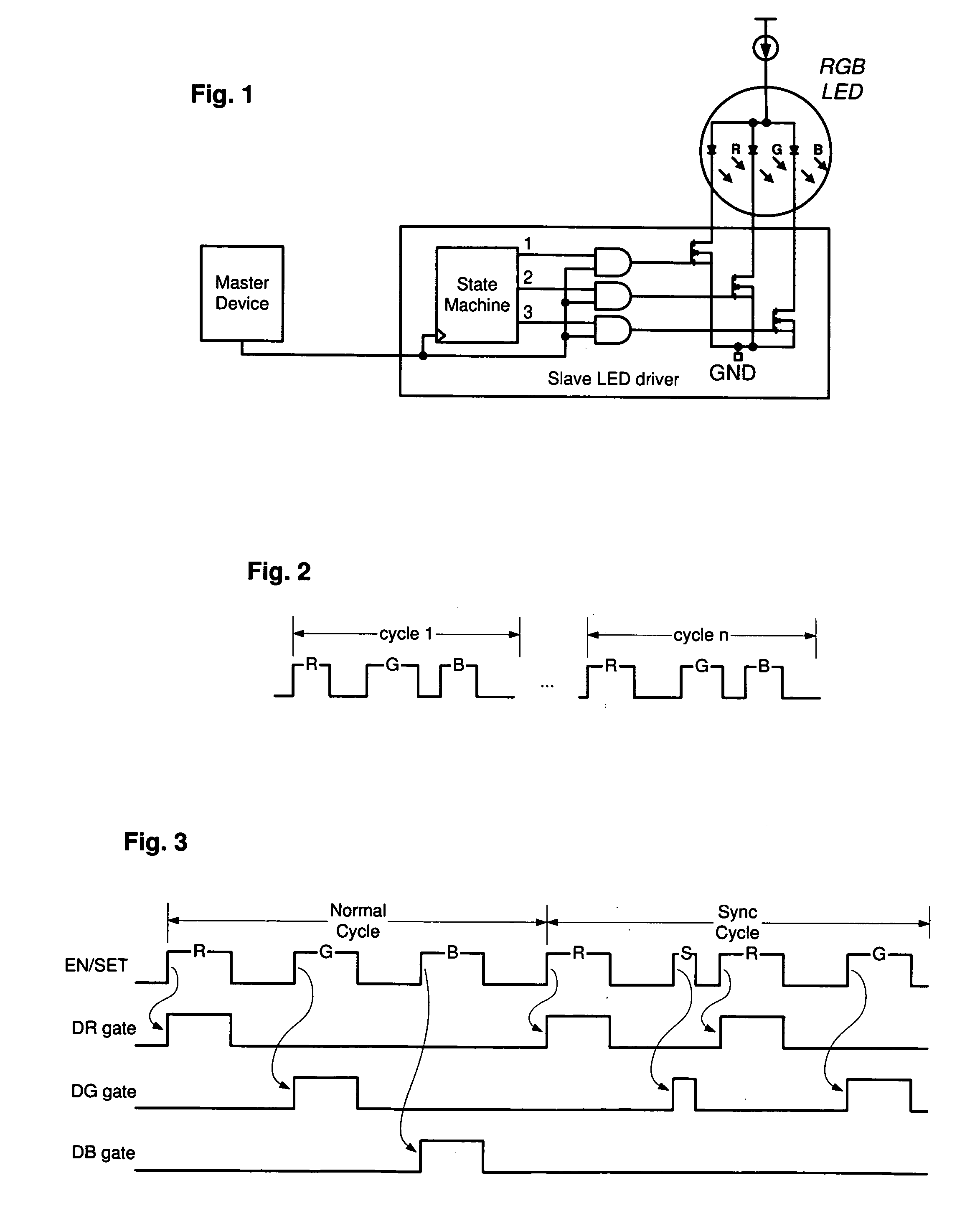
[0010] The present invention provides a method for RGB LED control using a single wire serial interface. For the control method, a master device controls the voltage on a serial line to encode a repeating series of variable width pulses. Each pulse in the series corresponds to red, green or blue colors. The red, green and blue pulses are interleaved in a repeating pattern: red, green, blue, red, green, blue and so on.
[0011] A state machine monitors the serial line and separates the repeating series into red, green and blue pulse trains. The state machine forwards each separate pulse train to the corresponding color element of an RGB LED. In effect, this provides each color element with a separate PWM control signal.
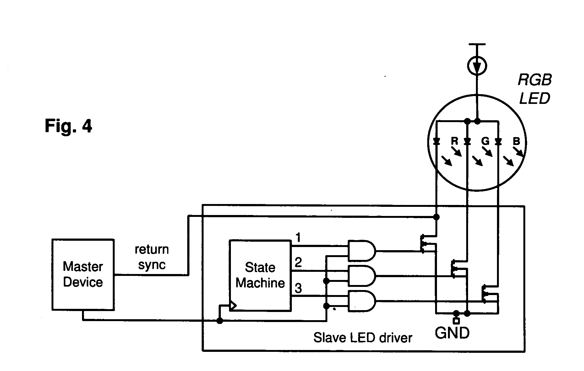
[0012] To ensure that the state machine and the master device operate synchronously, the master device controls the voltage on the serial line to encode a sync signal. The sync signal is a single pulse of short duration. The state machine detects the sync signal by its short duration and enters a known state. The master device may then resume the normal pattern of red, green and blue pulses. Depending on the particular implementation, it is possible for the master device to send the sync signal on a periodic basis. Alternately, the master device may be configured to detect an out-of-sync condition and send the sync signal in response.

Problems solved by technology

Unfortunately, the use of analog signals is inherently error prone and not always easy to calibrate.
It is also true that many microprocessors lack analog outputs, making implementation of analog control signals even more difficult.
However, even serial implementations typically require at least two (and often three) inputs leads.
Where input leads are scarce, the use of two to three leads may be difficult to accommodate.
In other cases, the use of two or three input signals may create complex routing problems between the driver and its controlling entity.
In particular, there is a possibility that a missed detection may result in a situation where demultiplexing preceded incorrectly and colors are incorrectly reproduced.

Method used


Image

  • Single wire serial protocol for RGB LED drivers
  • Single wire serial protocol for RGB LED drivers

Examples


Embodiment Construction

[0017] The present invention provides a method for RGB LED control using a single wire serial interface. As shown in FIG. 1, a typical implementation that uses this method includes a master device connected (via a single wire serial line) to a slave LED driver. The slave LED driver is connected, in turn to an RGB LED. Internally, the slave LED driver includes a state machine that translates signals on the serial line into signals that drive the RGB LED.

[0018] To control the RGB LED, the master device controls the voltage on the serial line to encode a repeating series of pulses. As shown in FIG. 2, the series of pulses are arranged in an interleaved pattern: red, green, blue, red, green, blue and so on. The width of each pulse is variable so, for example the red pulse in cycle n is longer than the red pulse in cycle 1. The green pulse in cycle n is also shorter than the green pulse in cycle 1.

[0019] The state machine in the slave LED driver demultiplexes this repeating pattern. Th...


PUM


Abstract

A method for RGB LED control includes toggling the voltage on a serial line to encode desired colors as a repeating series of variable width pulses. Each pulse in the series corresponds to red, green or blue colors. A state machine monitors the serial line and separates the repeating series into red, green and blue pulses. The state machine forwards each separate pulse to the corresponding color element of an RGB LED. In effect, this provides each color element with a separate PWM control signal. A synchronization method is provided to ensure that the state machine correctly decodes the repeating sequence of red, green and blue colors.

Description

TECHNICAL FIELD [0001] The present invention relates to drivers used to power light emitting diodes (LEDs) and other devices. More particularly, the present invention relates to efficient drivers for RGB LED applications in portable electronic systems. BACKGROUND OF THE INVENTION [0002] RGB LEDs are used in a wide range of portable electronic devices including cellular telephones, personal digital assistants and handheld games. A typical RGB LED includes separate red, green and blue light emitting diodes. The separate diodes are driven for different duty cycles (typically in series, one after the other) to generate different colors. A simple case is where red, green and blue diodes are each driven for the same period in succession to create the color white. [0003] To maximize battery life, it is typical for portable electronic devices to use specialized LED drivers. Drivers of this type supply LEDs with regulated power at the correct voltage even as battery voltage fluctuates or dec...

Claims


Application Information

Patent Timeline
Patent Type & Authority Applications(United States)
IPC IPC(8): H01L29/18
CPCH05B33/0818Y02B20/346H05B37/0254H05B33/0827H05B45/20H05B45/325H05B45/46H05B47/18Y02B20/30
Inventor D'ANGELO, KEVIN P.
Owner ADVANCED ANALOGIC TECHNOLOGIES INCORPORATED
Learn More