
Free flow conveyance system

a free flow and conveyancing technology, applied in the field of conveyancing systems, can solve the problems of long length of thus formed conveyance routes, low space efficiency, and unfavorable long-term maintenance, and achieve the effects of reducing troublesome work, simplifying line change work, and efficient conveyancing of a small number of various products

Active Publication Date: 2005-12-08
STARTECHNO
View PDF17 Cites 22 Cited by
  • Summary
  • Abstract
  • Description
  • Claims
  • Application Information

AI Technical Summary

Benefits of technology

[0010] It is therefore an object of the present invention to overcome the above-mentioned drawbacks by providing a free flow conveyance system that can convey a small number of various products efficiently, and can simplify the line change work to reduce troublesome works at the time of changing a conveyance line corresponding to products. Furthermore, another object of the present invention is to provide a free flow conveyance system that uses a small-sized electric motor with low-torque as a conveyance driving unit, and can reduce driving cost.

Problems solved by technology

That is, when constructing a conveyance system, a number of conveyance apparatuses having a long conveyance path are coupled to meet a required conveyance distance, which inevitably makes the length of thus formed conveyance route longer than a desired distance.
Thus, there arise many dead spaces, leading to low space efficiency.
Furthermore, when changing a conveyance line, large and heavy conveyance apparatuses having a long conveyance path have to be relocated, which is troublesome and requires much time undesirably.
Thus, even if the number of products is small, the electric motor has to be driven under the power corresponding to the maxim number of products to be conveyed, which undesirably increases electric power consumption, leading to high driving cost.

Method used


Image

  • Free flow conveyance system
  • Free flow conveyance system
  • Free flow conveyance system

Examples


Embodiment Construction

[0023] The present invention will be described below with reference to the accompanying drawings.

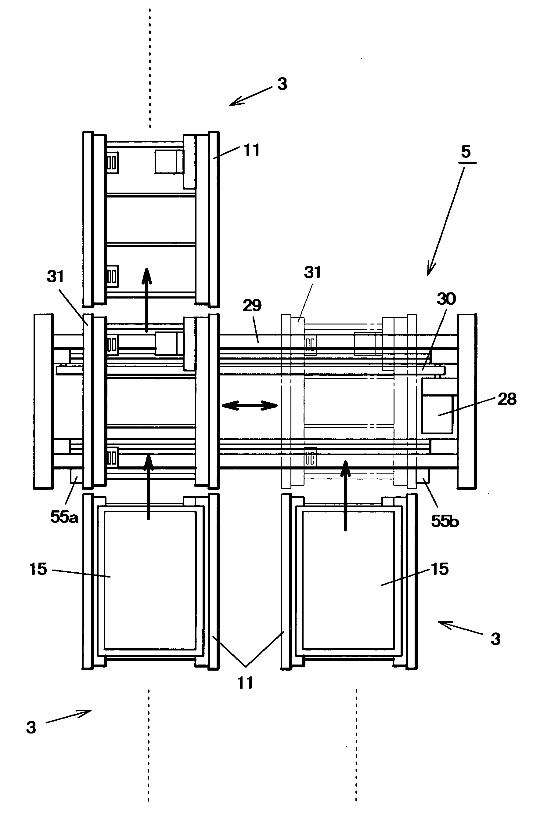
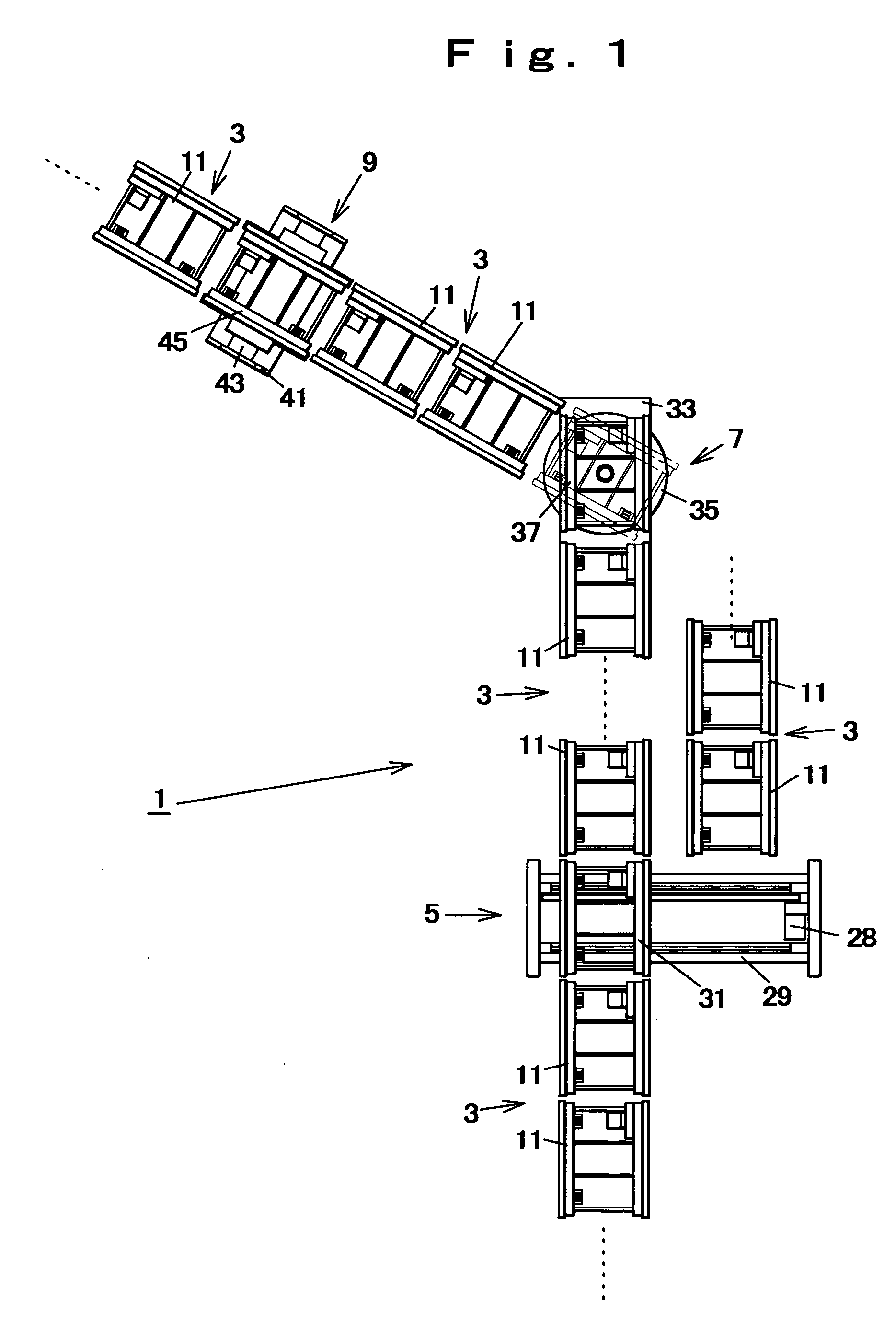
[0024] As shown in FIG. 1 to FIG. 5, a free flow conveyance system 1 according to the present invention includes a plurality of linear conveyance apparatuses 3 (specifically, the free flow conveyance system 1 has five linear conveyance apparatuses 3 that are referred to as the first to fifth linear conveyance apparatus 3 respectively), a divergent conveyance apparatus 5 that is arranged, for example, between the first linear conveyance apparatus 3 and the parallel arranged second and third linear conveyance apparatuses 3 to selectively direct the conveyance route from the first linear conveyance apparatus 3 either to the second linear conveyance apparatus 3 or to the third linear conveyance apparatus 3, a pivot conveyance apparatus 7 that is arranged, for example, between the third and fourth linear conveyance apparatuses 3 which are so arranged as to form a predetermined angle, and an ...


PUM


Abstract

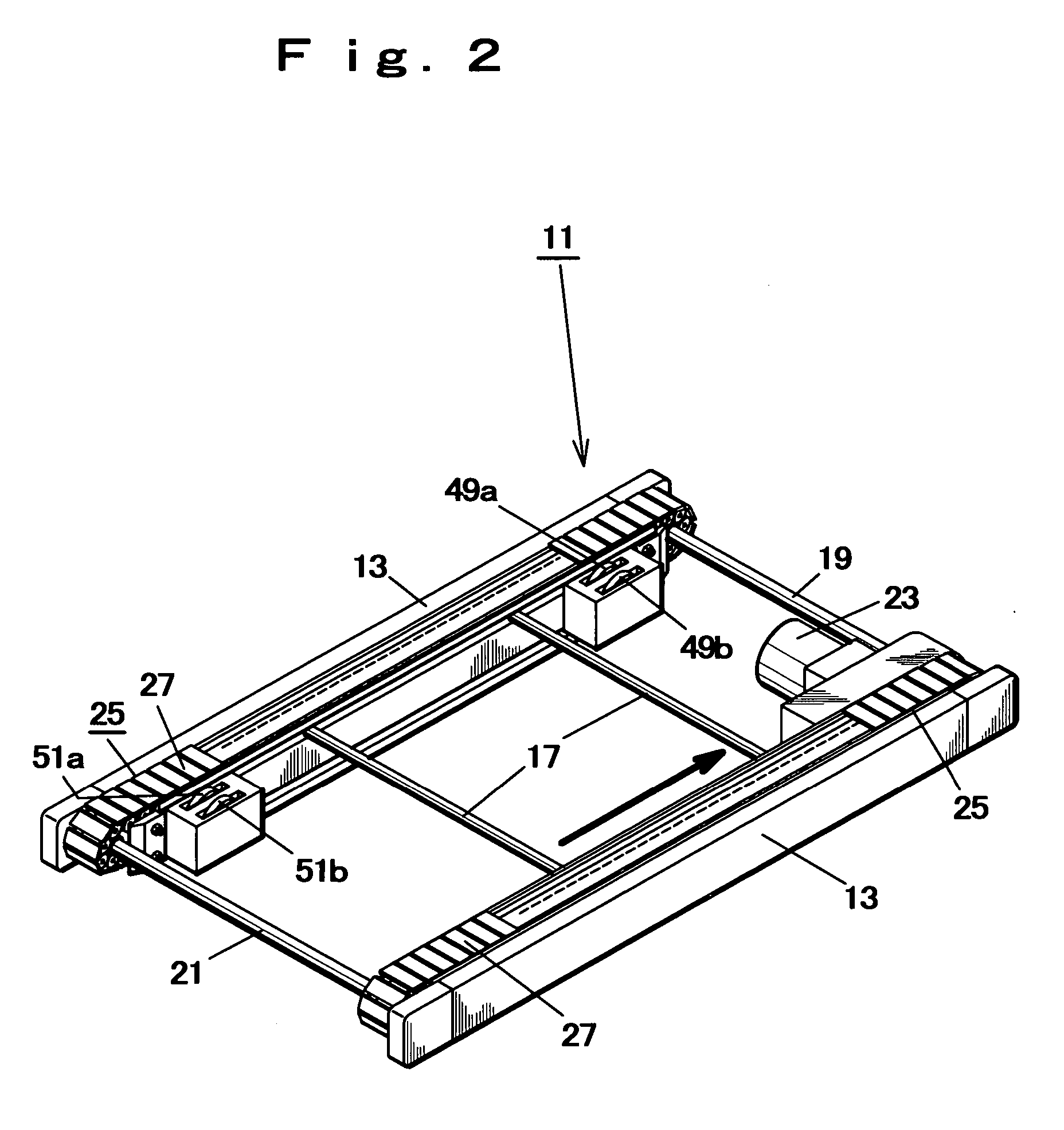
A free flow conveyance system includes a plurality of linear conveyance apparatuses each having a plurality of unit conveyors linearly arranged, and a pivot conveyance apparatus having a unit conveyor which is arranged between the linear conveyance apparatuses being so arranged as to form a predetermined angle, wherein product sensors are arranged at the conveying-in side as well as at the conveying-out side of the respective unit conveyors of the linear conveyance apparatuses and the pivot conveyance apparatus, when a product is conveyed to a unit conveyor of the upstream side along the conveyance direction and product sensors of the unit conveyor become of the sensing-product state, in case respective product sensors of a unit conveyor of the downstream side along the conveyance direction are of the not-sensing-product state, these unit conveyors are driven respectively to convey the product, and when the product is consequently conveyed to the unit conveyor of the downstream side along the conveyance direction and conveying-out side product sensors thereof become of the sensing-product state, the respective adjacent unit conveyors are stopped, enabling free flow conveyance.

Description

BACKGROUND OF THE INVENTION [0001] 1. Field of the Invention [0002] The present invention relates to a conveyance system that conveys products or pallets and containers having stored therein products (referred to as products, hereinafter) in the free flow manner. [0003] 2. Description of Related Art [0004] In the conventional conveyance system that conveys products, a number of conveyance apparatuses such as roller conveyors, belt conveyors, caterpillar conveyors, etc. whose conveyance path is longer than the length of products along the conveyance direction are coupled, and a lot of products are put on the conveyance apparatuses to be conveyed to desired locations. [0005] The conventional conveyance system, in which a number of conveyance apparatuses whose conveyance path is long are coupled to form a conveyance route, is suitable for conveying a large number of products, while raising the following problems when conveying a small number of various products. [0006] That is, when co...

Claims


Application Information

Patent Timeline
IPC IPC(8): B65G37/00B65G43/08B65G43/10B65G47/46B65G47/64
CPCB65G37/02B65G43/10B65G2207/30B65G47/643B65G47/648B65G47/642
Inventor ENYA, YOSHIHIRO
Owner STARTECHNO
Learn More