
Telescopic stepladder

Inactive Publication Date: 2005-12-08
LIN CHO SHIEN
View PDF10 Cites 18 Cited by
  • Summary
  • Abstract
  • Description
  • Claims
  • Application Information

AI Technical Summary

Benefits of technology

[0003] It is an object of the present, invention to provide a telescopic stepladder including two frames hingedly coupled to a top and two lower, folding braces respectively, either frame comprising a lowest support section; one or more sliding sections wherein two side rails of each section are interconnected by one or more steps; a plurality of locking mechanisms each disposed in either locking portion of two sections and including a fastener adapted to fasten the side rail of one section and the side rail of the other section together, and a lower spring depressible detent adapted to lock both sections; whereby pushing the braces upward, moving bo

Problems solved by technology

However, telescopic stepladders are not available as far as the present inventor is aware.
It is understood that a long stepl

Method used


Image

  • Telescopic stepladder
  • Telescopic stepladder
  • Telescopic stepladder

Examples


Embodiment Construction

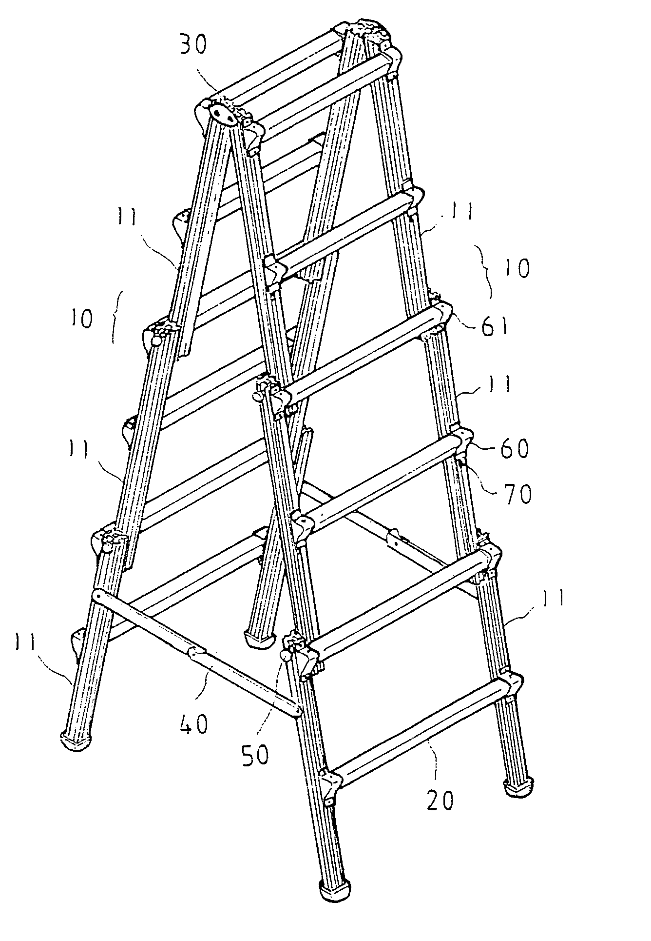
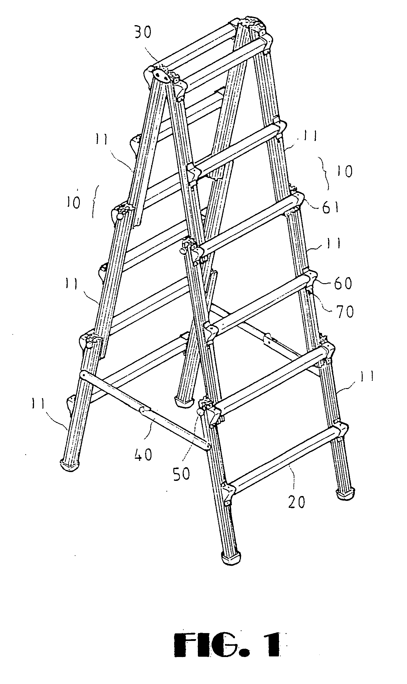
[0016] Referring to FIGS. 1 to 8, there is shown a telescopic stepladder constructed in accordance with the invention in which two frames 10 are jointed at a hinged top plate 30 and two braces 40 having toggle joint are hingedly coupled to the frames 10. Either frame 10 comprises a lowest support section 11 and two sliding sections 11. Side rails of each section 11 are interconnected by two steps 20.

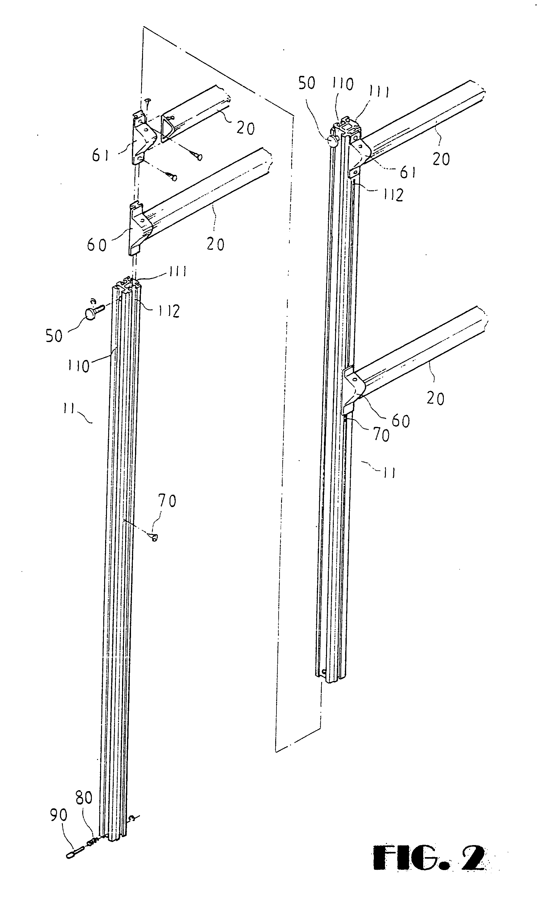
[0017] As shown in FIG. 6, the side rail 11 has a longitudinal groove 110 having a section of T at an outer side, a longitudinal projection 111 having a section of T at an inner side, and two longitudinal grooves 112 having a section of T at front and rear sides respectively. Either locking portion of two sections 11 comprises a second locking member 61 threadedly secured to the horizontal side rail 11 and the vertical step 20 in which the second locking member 61 has a longitudinal projection having a section of T matingly engaged with and threadedly secured to the front groove 112 of ...


PUM


Abstract

Either frame of a telescopic stepladder comprises a support section, one or more sliding sections, a plurality of locking mechanisms each disposed in either locking portion of two sections and in one embodiment including a fastener adapted to fasten the side rail of one section and the side rail of the other section together, and a lower spring depressible detent adapted to lock both sections. Pushing the braces upward, moving both frames toward each other, unfastening the fasteners, unlocking the detents, and sliding down the sliding sections to a limit will retract the sliding sections with respect to the support sections or the retracted sliding sections.

Description

FIELD OF THE INVENTION [0001] The present invention relates to stepladders and more particularly to a telescopic stepladder with improved characteristics. BACKGROUND OF THE INVENTION [0002] Extension ladders are well known. However, telescopic stepladders are not available as far as the present inventor is aware. It is understood that a long stepladder such as one having a height more than four meter is difficult of carrying for work if the stepladder is not telescopic. Thus, it is desirable to provide a novel telescopic stepladder in order to overcome the above drawback of prior art. SUMMARY OF THE INVENTION [0003] It is an object of the present, invention to provide a telescopic stepladder including two frames hingedly coupled to a top and two lower, folding braces respectively, either frame comprising a lowest support section; one or more sliding sections wherein two side rails of each section are interconnected by one or more steps; a plurality of locking mechanisms each dispose...

Claims


Application Information

Patent Timeline
IPC IPC(8): E06C1/00E06C1/18E06C1/22E06C7/06
CPCE06C1/18E06C7/083E06C7/06E06C1/22
Inventor LIN, CHO SHIEN
Owner LIN CHO SHIEN
Learn More