
One-piece molded corner flashing for dormers, roof offsets and chimneys

Inactive Publication Date: 2005-12-08
LANE STEVEN J +2
View PDF8 Cites 16 Cited by
  • Summary
  • Abstract
  • Description
  • Claims
  • Application Information

AI Technical Summary

Benefits of technology

[0009] As will become clear from the following description, the flashing of the present invention consists of one-piece molded plastic corner which precisely fits the outside corner of chimneys, dormers and roof offsets on pitched roofs ranging from 3 / 12 to 12 / 12 pitches. Because each flashing is molded to fit each particular roof pitch, an easy and water-tight installation is achieved, without any field modification or cutting—merely by selecting the appropriate one to match with the roof pitch. Including a horizontal plane, a front or rear vertical plane, and a side vertical plane, the angles between the planes change from roof-to-roof, as the roof pitch changes. With each plane being a minimum 5″×7″ in size, the overlapping of laid down shingles allows for an installation without gaps or seams which sits tightly on the roof. Requiring no field modification, the one-piece molded plastic corner flashing will be appreciated to meet all specifications of the National Roofing Contractors Association (NRCA).

Problems solved by technology

This oftentimes results in a flashing installation which is sloppily done.
In fact, experience has shown that almost 90% of those roof leaks that develop occur not at the body of the shingles, but at these corners, when the flashing fails.
Besides continuing to require a high degree of skill to overlap the sides in forming the tuck at a vertical corner, however, the suggestion there put forth provides only minimum protection at the point where the vertical planes and horizontal plane of the flashing intersect at the base.

Method used


Image

  • One-piece molded corner flashing for dormers, roof offsets and chimneys
  • One-piece molded corner flashing for dormers, roof offsets and chimneys
  • One-piece molded corner flashing for dormers, roof offsets and chimneys

Examples


Embodiment Construction

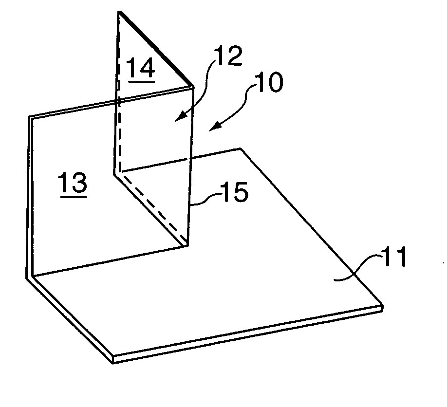
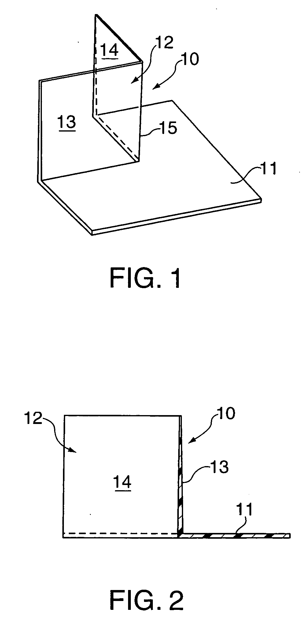
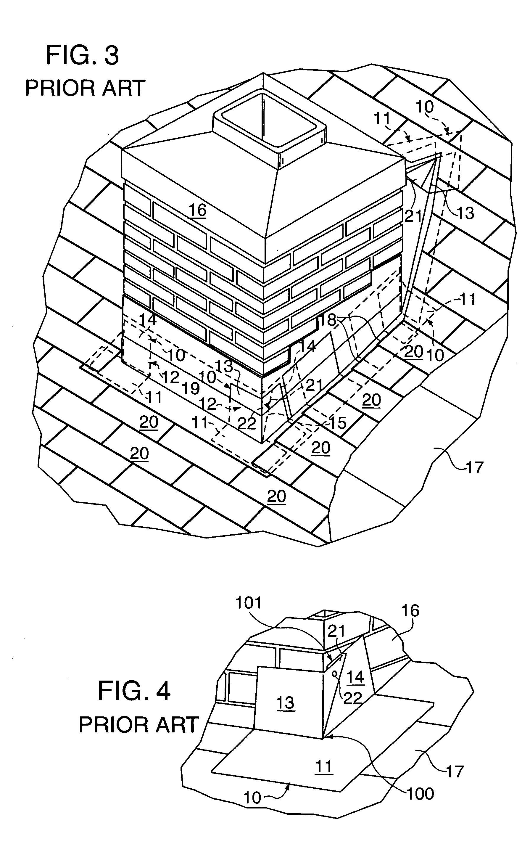
[0015] In the prior art drawings of FIGS. 1-4, the McGady corner flashing 10 includes a base 11 with an integral upstanding corner 12 having a pair of sides 13 and 14 in right-angled relation. With the sides integrally joined at a corner 15, the upstanding corner 12 is substantially in right angle relationship with the base 11.

[0016] As U.S. Pat. No. 5,077,943 describes, the base 11 is rectangular with parallel top and bottom edges, and parallel opposite sides intersecting at corners. The upper left-hand corner of the base 11 is notched out to provide a rectangular recess with edges which intersect at a corner spaced from the top, bottom and side edges of the base. The upstanding corner 12 forms a continuous junction with the base member that is coextensive with the recess, and the base 11 is “L”-shaped with leg portions radiating from sides 13 and 14 of the upstanding corner 12. Composed of a bendable plastic material, the flashing 10 is selected of a thickness so as to be suffici...


PUM


Abstract

A one-piece molded plastic flashing precisely fits outside corners of chimneys, dormers and roof offsets on pitched roofs ranging from 3 / 12 to 12 / 12 consisting of a horizontal roof plane, and a pair of vertical planes, angled with respect to one another to match with the pitch of the roof.

Description

CROSS-REFERENCE TO RELATED APPLICATIONS [0001] NONE STATEMENT REGARDING FEDERALLY SPONSORED RESEARCH OR DEVELOPMENT [0002] Research and development of this invention and Application have not been federally sponsored, and no rights are given under any Federal program. REFERENCE TO A MICROFICHE APPENDIX [0003] NOT APPLICABLE BACKGROUND OF THE INVENTION [0004] 1. Field of the Invention [0005] This invention relates to the prevention of leakage at the corner intersection of roof penetrations—such as at those locations where chimneys exit through the roof and where dormers meet the slanted plane of the roof. More particularly, the invention represents an improvement over the corner flashing shown in U.S. Pat. No. 5,077,943 to McGady, issued Jan. 7, 1992. [0006] 2. Description of the Related Art [0007] As will be appreciated, at these intersections, a roofing contractor conventionally trims a piece of flashing into a corner so that a waterproof envelope is provided by the shingles of the ...

Claims


Application Information

Patent Timeline
IPC IPC(8): E04D13/14E04D13/147
CPCE04D13/1475
Inventor LANE, STEVEN J.HINZ, KRYSTIAN M.SHEA, GERARD
Owner LANE STEVEN J
Learn More