
Mobile robot and system and method of compensating for path diversions

a mobile robot and path technology, applied in the direction of carpet cleaners, cleaning using liquids, instruments, etc., can solve the problems of deteriorating a working efficiency, mobile robots may deviate from the programmed working path, and errors between estimated travel angles

Inactive Publication Date: 2005-12-01
SAMSUNG GWANGJU ELECTRONICS CO LTD
View PDF5 Cites 33 Cited by
  • Summary
  • Abstract
  • Description
  • Claims
  • Application Information

AI Technical Summary

Benefits of technology

[0016] According to yet another aspect of the present invention, there is provided a method for compensating a path of a mobile robot, comprising the steps of storing initial polar-mapping image data obtained by polar-mapping an initial ceiling image photographed by a vision camera; changing a traveling angle of the mobile robot, so that the mobile robot is diverted according to at least one of a working path programmed in advance and an obstacle; while the robot cleaner changes the traveling angle, determining whether the rotation angle of the mobile robot corresponds to at least one of directions; a traveling direction according to a preset working path and a traveling direction for avoiding an obstacle, by comparing the initial polar-mapping image data with real-time polar-mapping image data, obtained by polar-mapping the ceiling image photographed real time or at regular intervals by the vision camera; and stopping changing of the traveling angle of the mobile robot when the traveling angle of the mobile robot corresponds to the at least one of the directions; a traveling direction according to a preset working path and a traveling direction for avoiding an obstacle.

Problems solved by technology

However, when the encoder recognizes the current location and detects the rotation angle, an error may occur between an estimated travel angle, which is calculated by a signal that the encoder detects, and an actual travel angle, due to slip of the wheel and unevenness of a floor surface during the travel.
The error of the detected rotation angle is accumulated as the mobile robot travels, and accordingly, the mobile robot may deviate from the programmed working path.
As a result, the mobile robot may fail to completely perform its work in the working area or repeat the work in only a certain area, thereby deteriorating a working efficiency.
However, the accelerometer or the gyroscope increases manufacturing cost.

Method used


Image

  • Mobile robot and system and method of compensating for path diversions
  • Mobile robot and system and method of compensating for path diversions
  • Mobile robot and system and method of compensating for path diversions

Examples


first embodiment

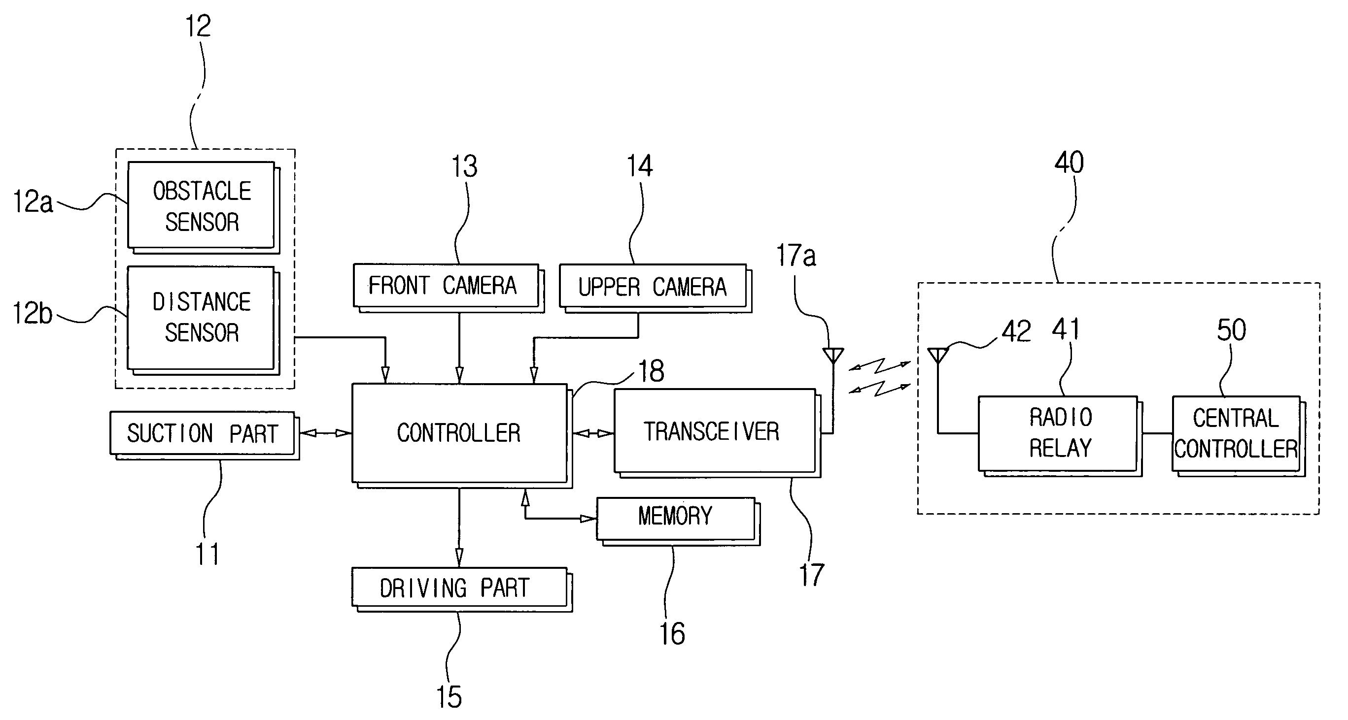
[0059] Hereinbelow, a method for compensating a path of the robot cleaner 10, according to the present invention, will be described in greater detail with reference to FIG. 7.

[0060] In step S1, the controller 18 determines whether an operation requesting signal is received by the robot cleaner 10.

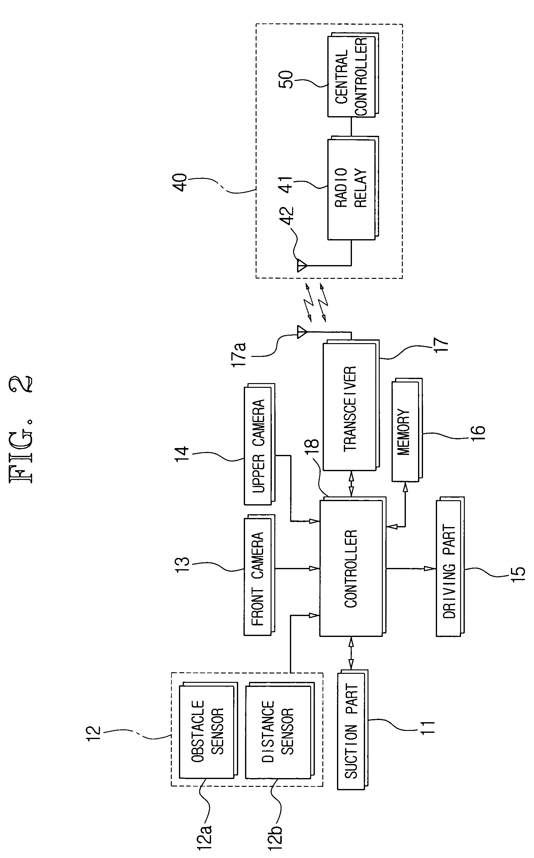
[0061] If an operation requesting signal is received by the controller 18, the controller 18 transmits a traveling command and a sensing signal to the driving part 15 and the sensor 12.

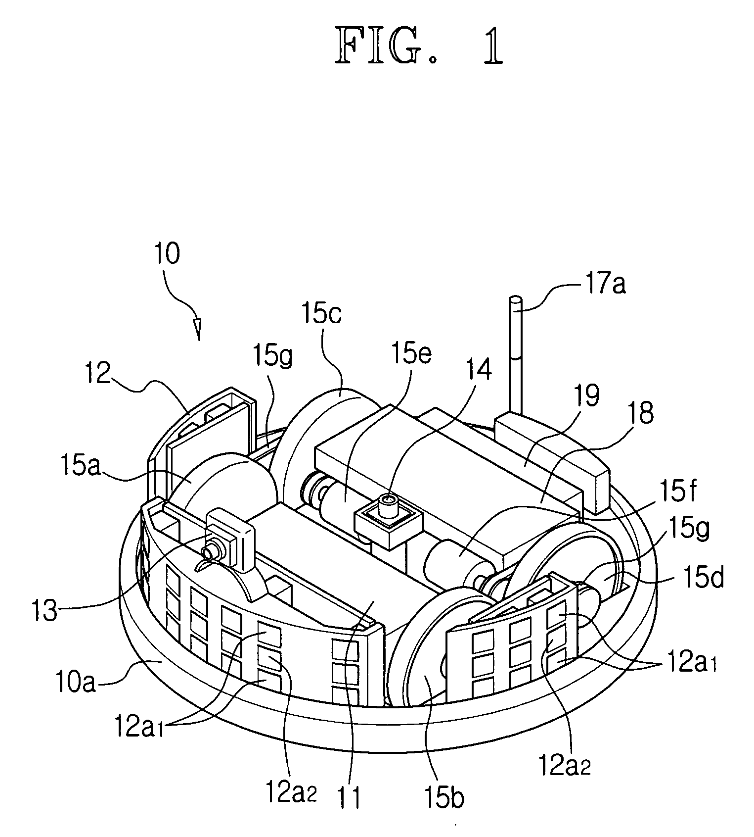
[0062] In step S2, the aforementioned driving part 15 drives the motors 15e and 15f according to the signal of the controller 18 and starts the robot cleaner 10 traveling along a working path that is programmed in advance.

[0063] The obstacle sensor 12a and the distance sensor 12b transmit a sensing signal to the controller 18.

[0064] In step S3, while the robot cleaner 10 is traveling, the controller 18 determines whether the obstacle sensor 12a detects any obstacles such as the walls 61 and 61′ and decide...

second embodiment

[0072] Hereinbelow, a method for compensating a working path of the robot cleaner 10 according to the present invention will be described in greater detail with reference to FIG. 8.

[0073] In step S1, the controller 18 determines whether an operation requesting signal is received by the robot cleaner 10 that has been standing at a certain location through the key input device or wirelessly from the outside (S1), and performs processes of S2 to S4 as in the first embodiment of the compensating method.

[0074] After step S4, the controller 18 transmits to the motors 15e and 15f a command for diverting the robot cleaner 10 in accordance with the traveling angle of the programmed working path and changes the traveling angle of the robot cleaner 10. Also, while the robot cleaner 10 changes the traveling angle by the driving part 15, the controller 18 photographs the ceiling image 60′ real time or at regular intervals by the upper vision camera 14, extracts the polar-mapping image 60A′ by c...


PUM


Abstract

A mobile robot measures a rotation angle using information from an image photographed by a vision camera. A mobile robot system comprises a main body of the robot, a driving part for driving a plurality of wheels; a vision camera mounted on a main body thereof to photograph an upper image which is perpendicular to a traveling direction; and a controller for calculating a rotation angle using polar-mapping image data obtained by polar-mapping a ceiling image, photographed by the vision camera, with respect to a ceiling of a working area. The controller drives the driving part using a calculated rotation angle. The rotation angle is measured by the vision cameras and the rotation angle can be used to compensate the working path, without having to provide expensive devices such as an accelerometer or a gyroscope, thereby saving manufacturing cost.

Description

CROSS-REFERENCE TO RELATED APPLICATIONS [0001] This application claims the benefit of Korean Patent Application No. 2004-34364, filed May 14, 2004, in the Korean Intellectual Property Office, the disclosure of which is incorporated herein by reference. FIELD OF THE INVENTION [0002] The present invention relates generally to a mobile robot, which automatically travels around, a mobile robot system, and a method of compensating for path diversions thereof. More particularly, the present invention relates to a mobile robot that measures a rotation angle using information from an image photographed by a vision camera, thereby compensating for path diversions of the robot, and a mobile robot system. BACKGROUND OF THE INVENTION [0003] In general, a mobile robot defines a working area surrounded by walls or obstacles using an ultrasonic wave sensor mounted in a main body thereof and travels along a working path programmed beforehand, thereby performing a main operation such as a cleaning w...

Claims


Application Information

Patent Timeline
IPC IPC(8): A47L9/00A47LA47L9/28A47L11/40B25J5/00B25J9/16B25J13/08B25J19/00B25J19/04G05B1/01G05D1/02
CPCG05D1/0242G05D1/0246G05D1/0253G05D2201/0203G05D1/027G05D1/0272G05D1/0274G05D1/0255A47L9/009B08B3/02B08B2203/02B08B2203/007A47L9/00A47L11/4011A47L11/4061A47L2201/04A47L11/40A47L2201/00G05D1/249G05D1/246
Inventor LEE, JU-SANGKO, JANG-YOUNSONG, JEONG-GONLIM, KWANG-SOOKIM, KI-MANJEUNG, SAM-JONG
Owner SAMSUNG GWANGJU ELECTRONICS CO LTD
Learn More