Input device including a wheel assembly for scrolling an image in multiple directions

a technology of input device and image, which is applied in the direction of instruments, cathode-ray tube indicators, computing, etc., can solve the problems of changing the displayed image, small display screen and/or poor hand-eye coordination, and difficult to locate the scroll bar

Inactive Publication Date: 2005-12-01
MICROSOFT TECH LICENSING LLC
View PDF2 Cites 15 Cited by
  • Summary
  • Abstract
  • Description
  • Claims
  • Application Information

AI Technical Summary

Benefits of technology

[0013] The device according to the present invention makes it easy for a user to scroll an image both horizontally and vertically relative to a display screen without repositioning the peripheral device. Additionally, the different types of wheel movements used by the present invention to cause scrolling in the perpendicular directions eliminate problems and frustrations that may result from using the prior art devices.
[0019] In another aspect relative to the scrolling device, a cover having an aperture therein. A portion of the scrolling member extends through the aperture and an opening in the housing. The scrolling cover is tiltable with the scrolling member. This cover closes the area around the opening in the housing and protects internal components from dust and other substances. The cover may include convexly curved sides.

Problems solved by technology

Locating the scroll bar can be very difficult for people with bad eyesight, small display screens and / or poor hand-eye coordination.
Even if the size of the horizontal scroll bar and / or the screen resolution can be adjusted, the user must nevertheless perform additional pointing tasks which are more time-consuming and mentally intensive than simply rotating a wheel or pushing a button.
Or, when using the mouse wheel, the image will move vertically relative to the display screen and erroneously change the displayed image.
These errors will force the user to take additional steps to reposition the desired image on the display screen.
Unfortunately, repositioning an image can lead to errors if the image is being amended.
As a result, he may amend the wrong section of the image.
However, this arrangement has drawbacks.
The smaller sized scroll wheels make the scrolling more difficult to control.
Additionally, the location of the horizontal scroll wheel can be inconvenient for effective control.
Further, with this design, it might be difficult for some users to easily reach and manipulate both of the wheels.

Method used


Image

  • Input device including a wheel assembly for scrolling an image in multiple directions
  • Input device including a wheel assembly for scrolling an image in multiple directions
  • Input device including a wheel assembly for scrolling an image in multiple directions

Examples


second embodiment

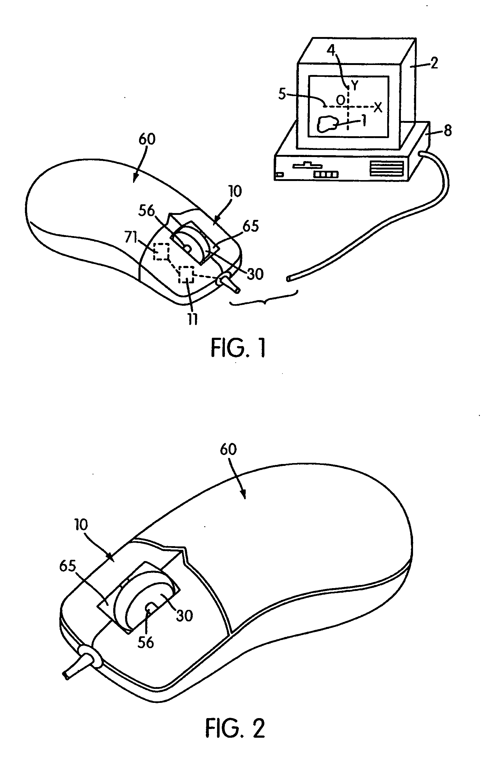
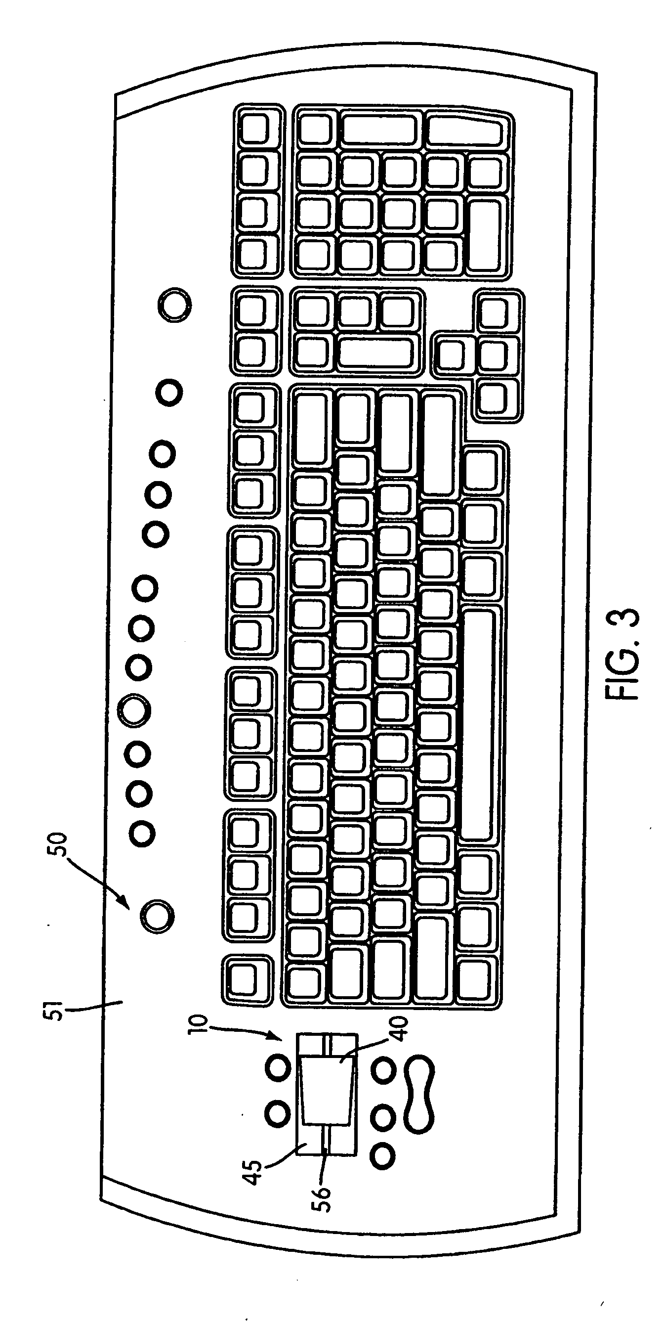
[0054] As shown in FIG. 2, one embodiment of the scroll wheel assembly 10 comprises a rotatable member, such as a circular disk-shaped scroll wheel 30 positioned within an elongated opening 65 in a housing 61 of the mouse 60. A portion of the wheel 30 protrudes away from the outer surface of the mouse 60 so that it can be contacted and manipulated by a user. In a second embodiment, shown in FIG. 3, the rotatable member of the scroll wheel assembly 10 includes an elongated cylindrically shaped wheel 40 secured within an opening 55 of a housing 51 for the keyboard 50. Like the disk-shaped wheel 30, a portion of the cylindrically shaped wheel 40 protrudes above the keyboard 50 outer surface so that it can be easily contacted and manipulated by a user.

[0055] Other shapes capable of rotating relative to a housing can also be used for the rotatable members of the scroll wheel assembly 10. For example, wheel 40 could have a circular cross section of constant diameter as shown in FIG. 4. Al...

first embodiment

[0059] The shaft 56 may be coupled to the peripheral device 50, 60 in any desired manner that achieves the described functionality. FIG. 7 illustrates a first embodiment where, a first end 57 and a second end 58 of the shaft 56 are each rotatably and slidably received within support stands 59 with U-shaped openings, rings attached to the interior surface of the housing 51 or other similar supports that permit the shaft 56 to rotate and slide along the axis 52 relative to the keyboard housing 51. Similarly, the supports 59 could also be positioned along the length of shaft 56 so that they are spaced from ends 57, 58.

[0060] According to the present invention, when the user wants to scroll the image 1 on the display screen 2 in multiple directions along multiple axes 4, 5, he or she will both rotate and / or laterally move the wheel 40 relative to the keyboard housing 51 to produce vertical and / or lateral scrolling, respectively. In a manner known in the art, when the cylindrical shaped ...


PUM


Abstract

A computer input device having a housing and a finger-engagable scrolling device. A portion of the scrolling device is endlessly rotatable about a first axis to preferably cause vertical scrolling of an image on a display. The scrolling device is pivotally movable relative to the housing about a second axis perpendicular to the first axis. The portion of the scrolling device may further be depressed to activate a switch.

Description

CROSS REFERENCE TO RELATED APPLICATIONS [0001] This application is a Continuation of U.S. patent application Ser. No. 11 / 094,139, filed Mar. 31, 2005, incorporated herein in its entirety, which is a Continuation of U.S. patent application Ser. No. 10 / 184,000, filed Jun. 28, 2002, incorporated herein in its entirety, which is a Continuation-in-Part application of U.S. patent application Ser. No. 09 / 843,794, filed Apr. 30, 2001, which is hereby incorporated by reference in its entirety.FIELD OF THE INVENTION [0002] The present invention relates to an input device including an assembly for moving an image in multiple directions on a display screen. More particularly, the present invention relates to a scroll wheel assembly that, when part of a peripheral or integral input device that is operatively connected to a host computer, can move an image in multiple axes relative to the display screen. BACKGROUND OF THE INVENTION [0003] Scroll wheels have been provided on computer mice and used...

Claims


Application Information

Patent Timeline
Patent Type & Authority Applications(United States)
IPC IPC(8): G06F1/16G06F3/02G06F3/033G06F3/048G09G5/08
CPCG06F3/0213G06F3/0312G06F3/0485G06F3/03543G06F3/0362G06F3/0338
Inventor LEDBETTER, CARL J.LINDHOUT, DAANADAMS, ADITHAMCLOONE, HUGH E.MUSS, TIMOTHY MICHAELKOO, JAMES Y.GARCIA, GINO
Owner MICROSOFT TECH LICENSING LLC
Why Eureka
Try Eureka