
Fish stringer system

a stringer and fish technology, applied in the field of fish stringing system, can solve the problem that stringers require more time to secure their catch

Active Publication Date: 2005-12-01
BRULL DWIGHT JOSEPH
View PDF11 Cites 3 Cited by
  • Summary
  • Abstract
  • Description
  • Claims
  • Application Information

AI Technical Summary

Benefits of technology

[0014] It is therefore an object of the present invention to provide an improved fish stringing system comprising a connector receptacle, and its' machined counterpart, designed to (simplify and hasten) the removal and replacement process of a fisher-persons' fish stringer.
[0017] As per these specifications, this invention will eliminate some of the hassles and physical manipulation of a “wade fisher-persons” equipment duties, during the event of securing their catch.

Problems solved by technology

However, these fish stringers require more time spent on securing ones catch.

Method used


Image

  • Fish stringer system
  • Fish stringer system
  • Fish stringer system

Examples


Embodiment Construction

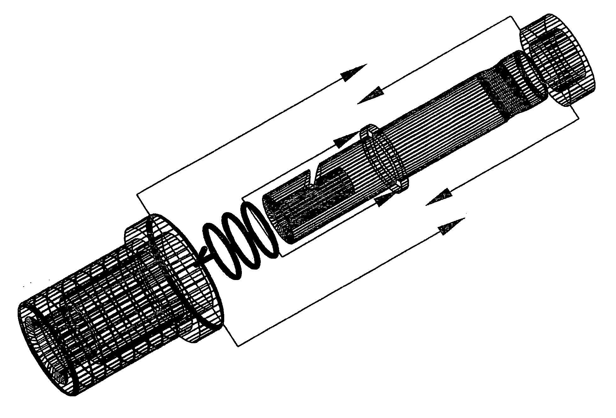
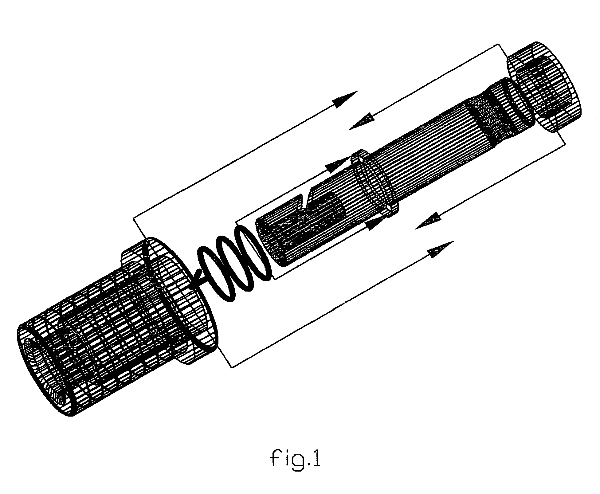
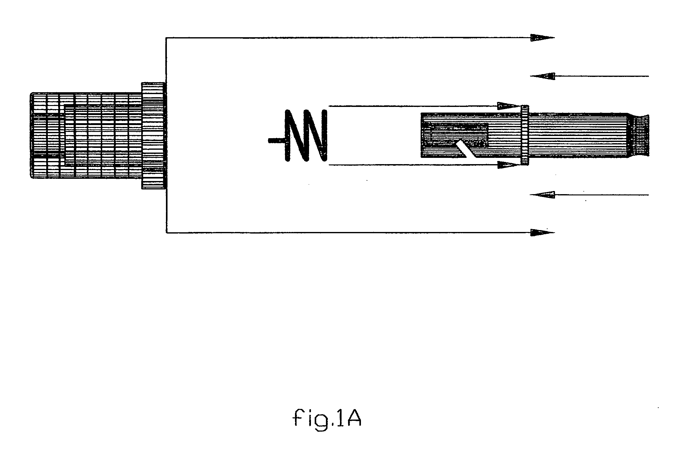
[0043] A spring of helical shape and design 23, with the perpendicular member 23A, is the basis of the operation of this particular “Fish Stringing System”.

[0044] For the sake of this explanation and detail description, the “Fish Stringing System” will be assumed to be in a vertical position.

[0045] THE EXTRACTION PROCESS: When opposite and opposing forces are applied to the perpendicular member 23A by applying force on the heightened ridge 21B of the shaft housing 21 and shaft *22 bottom. (such as one would apply, the same said forces, to a hypodermic syringe to administer its' product), the internal machined housing ridge 21A comes in contact (and forces) the perpendicular member 23A of spring 23 down and along the path of the diagonal slot 22A until it is (disengaged) free and clear of the machined (filleted / bullet) designed end of the stringer rod 25A; thus making the stringer rod able to be extracted without restriction.

[0046] THE INSERTION PROCESS: The force applied to inser...


PUM


Abstract

The quick connector receptacle, and its' machined counterpart, is designed to (simplify and hasten) the removal and replacement process of a fish stringer from its' affixed position. The process of securing a fisher-persons' bounty was addressed for specifically the intentions of making said process less of a task. Many variables can at times and under certain conditions, make said process complicated. The connector receptacle is affixed to the fisher-person and its' machined counterpart is disengaged and engaged to form an assemblage that holds said stringer in place until called upon for use again. In conjunction with the need of high quality materials to withstand the elements, particular interest was paid to all aspects of the system to make it durable. With much field-testing and some limited exposure, we believe it to be superior to the conventional stringer system. There appears to be a need for such a fish stringer system. With the particular parts and processes mentioned throughout this applications, said system will fulfill this need and prove to be a reliable system for the intended task.

Description

BACKGROUND OF THE INVENTION [0001] 1. Field of the Invention [0002] This invention relates to a fish stringing system, and more particularly, to a fish stringing system comprising two assemblies, a connector receptacle, and its' machined counterpart, designed to (simplify and hasten) the removal and replacement process of stringing fish to a fisher-persons' fish stringer while in the field. [0003] The applicable U.S. patent classification No. 403 / 321; 403 / 325; 224 / 103; 224 / 200; are in close relationship of said invention. [0004] 2. Description of the Related Art [0005] Fishing is a favorite pastime for many people around the world. Whether it be for relaxation or for excitement, it is for the enjoyment of the sport. The fish stringer, most commonly used to secure and transport the fish from the water to land or boat. However, these fish stringers require more time spent on securing ones catch. Most stringers devices are constructed whereby one end has to be tied to the wade fisher-p...

Claims


Application Information

Patent Timeline
IPC IPC(8): A01K1/00A01K65/00
CPCA01K65/00
Inventor BRULL, DWIGHT JOSEPH
Owner BRULL DWIGHT JOSEPH
Learn More