
A/D converter, D/A converter and voltage source

a technology of d/a converters and converters, applied in the direction of digital-analog converters, physical parameters compensation/prevention, instruments, etc., can solve the problems of lowering the manufacturing yield of a/d converters, d/a converters or voltage sources utilizing d/a converters, and the user of a/d converters cannot know the reference voltage at the time, so as to facilitate the generation of measurement voltage, improve the manufacturing yield of voltage sources, and accurate output voltag

Active Publication Date: 2005-11-24
SOCIONEXT INC
View PDF6 Cites 7 Cited by
  • Summary
  • Abstract
  • Description
  • Claims
  • Application Information

AI Technical Summary

Benefits of technology

[0011] It is an object of the present invention to provide an A / D converter from which a digital value representing an analog input voltage accurately is obtainable irrespective of the accuracy of a reference voltage. It is another object of the present invention to provide a D / A converter capable of generating an accurate analog output voltage irrespective of the accuracy of a reference voltage. It is still another object of the present invention to provide a voltage source capable of generating an accurate output voltage irrespective of the accuracy of a reference voltage. It is yet another object of the present invention to improve manufacturing yields of A / D converters, D / A converters, and voltage sources.

Problems solved by technology

Therefore, the user of the A / D converter cannot know a value of the reference voltage at the time of the A / D conversion.
If there is an A / D converter with the reference voltage of a range not trimmed within the standard range, it is regarded as defective, resulting in a lowered manufacturing yield of A / D converters.
Such a problem also occurs in D / A converters or voltage sources utilizing the D / A converters.

Method used


Image

  • A/D converter, D/A converter and voltage source
  • A/D converter, D/A converter and voltage source
  • A/D converter, D/A converter and voltage source

Examples


Embodiment Construction

[0046] Hereinafter, embodiments of the present invention will be described, using the drawings.

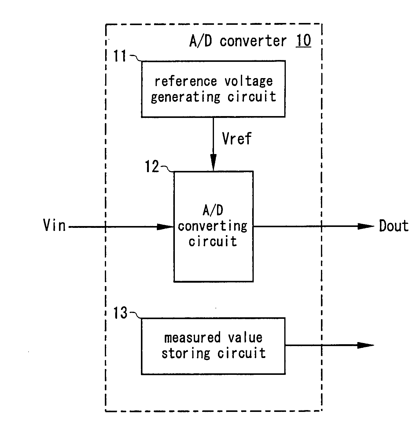
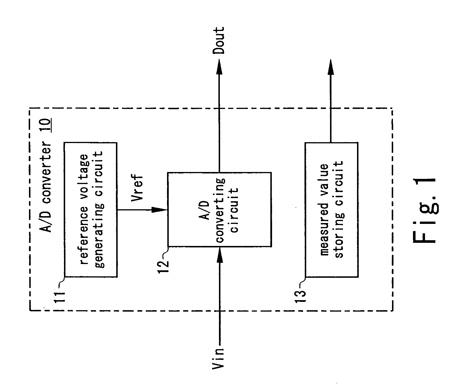
[0047]FIG. 1 shows a first basic principle of the A / D converter of the present invention. An A / D converter 10 has a reference voltage generating circuit 11, an A / D converting circuit 12, and a measured value storing circuit 13. The reference voltage generating circuit 11 generates a reference voltage Vref to output it to the A / D converting circuit 12. The A / D converting circuit 12 compares an analog input voltage Vin with the reference voltage Vref to convert the analog input voltage Vin to a digital output value Dout and outputs the digital output value Dout. The measured value storing circuit 13 stores a measured value of the reference voltage Vref in advance and outputs the stored measured value.

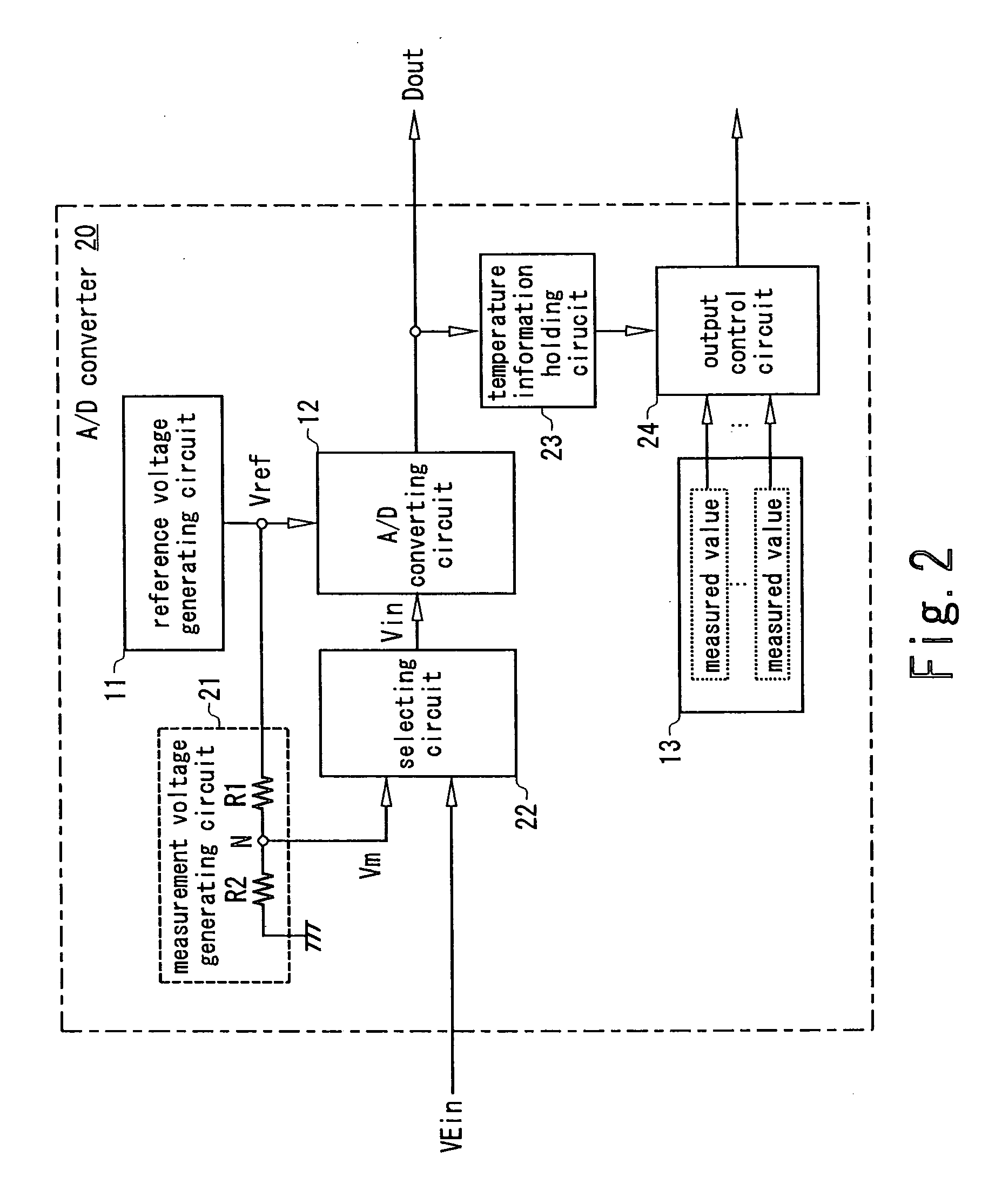
[0048]FIG. 2 shows a second basic principle of the A / D converter of the present invention. The same reference numerals and symbols are used to designate the same elements as the elements descr...


PUM


Abstract

A reference voltage generating circuit generates a reference voltage Vref. An A / D converting circuit compares an analog input voltage Vin with the reference voltage Vref to convert the analog input voltage Vin to a digital output value Dout. A measured value storing circuit stores a measured value of the reference voltage Vref in advance and outputs the stored measured value. A user of an A / D converter corrects the digital output value Dout from the A / D converting circuit by use of the measured value of the reference voltage Vref outputted from the measured value storing circuit, thereby obtaining a digital value representing the analog input voltage Vin accurately irrespective of the accuracy of the reference voltage Vref.

Description

CROSS REFERENCE TO RELATED APPLICATION [0001] This application is based upon and claims the benefit of priority from Japanese Patent Application No. 2004-151438, filed on May 21, 2004, the entire contents of which are incorporated herein by reference. BACKGROUND OF THE INVENTION [0002] 1. Field of the Invention [0003] The present invention relates to an A / D converter converting an analog input voltage to a digital output value, a D / A converter converting a digital input value to an analog output voltage, and a voltage source utilizing the D / A converter. [0004] 2. Description of the Related Art [0005] An A / D converter compares an analog input voltage with a reference voltage and converts the analog input voltage to a digital output value based on a ratio of the analog input voltage and the reference voltage. For example, a digital output value Dout of a 10-bit A / D converter is expressed by the following expression (1), where an analog input voltage is Vin and a reference voltage is V...

Claims


Application Information

Patent Timeline
Patent Type & Authority Applications(United States)
IPC IPC(8): H03M1/10H03M1/06H03M1/12H03M1/36H03M1/66
CPCH03M1/0621H03M1/66H03M1/12H03M1/10
Inventor ARIMURA, KAZUYOSHIHAYAKAWA, ATSUSHIOZAWA, HIDEKIYO
Owner SOCIONEXT INC
Learn More