
Apparatuses, systems and methods for bone fixation

a technology of bone fixation and apparatus, applied in the field of bone fixation, can solve the problems of preventing successful or optimal outcomes, affecting pain and functional outcomes, and affecting the need for reducing operative time,

Inactive Publication Date: 2005-11-10
INTEGRA LIFESCI
View PDF17 Cites 229 Cited by
  • Summary
  • Abstract
  • Description
  • Claims
  • Application Information

AI Technical Summary

Problems solved by technology

Open reduction internal fixation (ORIF) is a developed art with respect to some portions of the body; however, many complications can exist which can prevent successful or optimal outcomes in all cases utilizing ORIF.
Treatment methods can also significantly impact healing time, pain and functional outcomes.
Moreover, the necessity of reducing operative time is driven both by patient risk of infection, and aesthetic complications, and health care costs.
Prominence of hardware, leading to soft tissue abrasion and general inflammation.
If the fixation apparatus is, however, only able to grasp one cortice, and in a normal case, the proximal cortice, rotational alignment is not firmly engaged between the fixation apparatus and the plate and accurate reduction of the fixation site may not be maintained.
This problem is also common in the areas of the body not involving particularly long bones, such as the hand, foot and spine.
This problem also commonly exists in unhealthy (rheumatoid or osteoporotic) bone that simply cannot purchase bone as firmly as healthy bone.
Compression of bone with the screw independent of locking the screw in place is either not possible or is limited.

Method used


Image

  • Apparatuses, systems and methods for bone fixation
  • Apparatuses, systems and methods for bone fixation
  • Apparatuses, systems and methods for bone fixation

Examples


Embodiment Construction

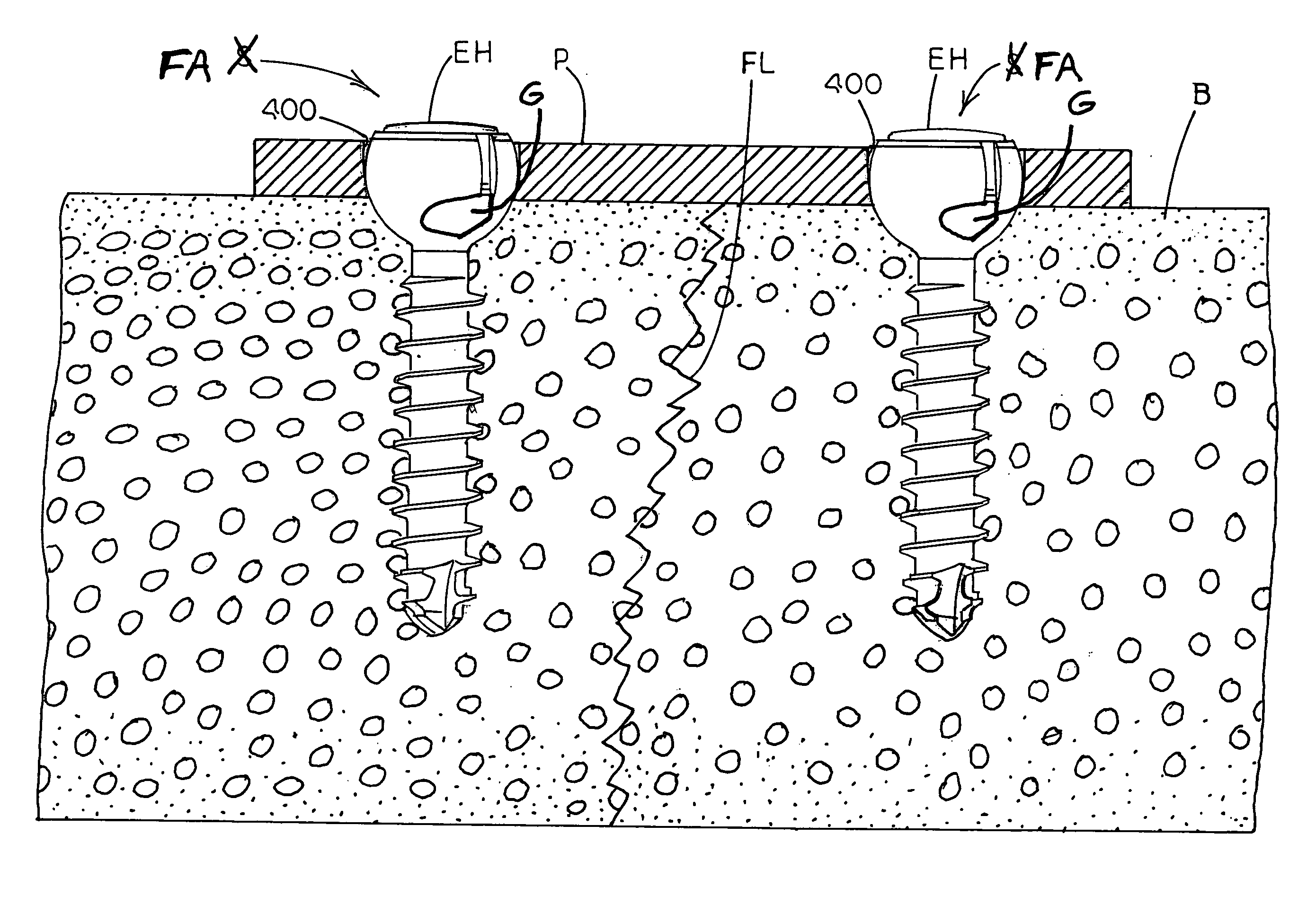
[0040] In accordance with the subject matter disclosed herein, and with reference to the various figures of drawings, apparatuses, systems and methods are provided for fixating a fractured bone with the ability to establish and maintain accurate alignment and reduction of bone fragments as well as to maintain such reduction through the healing process. As described in detail hereinbelow, a fixation apparatus in accordance with the present disclosure can be utilized in association with a plate in order to achieve and maintain desired alignment, independent of the level of fixation, in order to facilitate healing of a bone fracture.

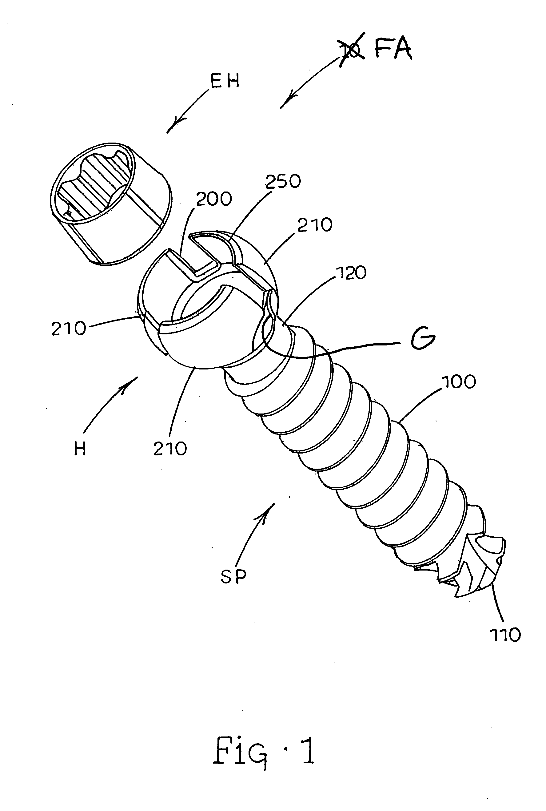
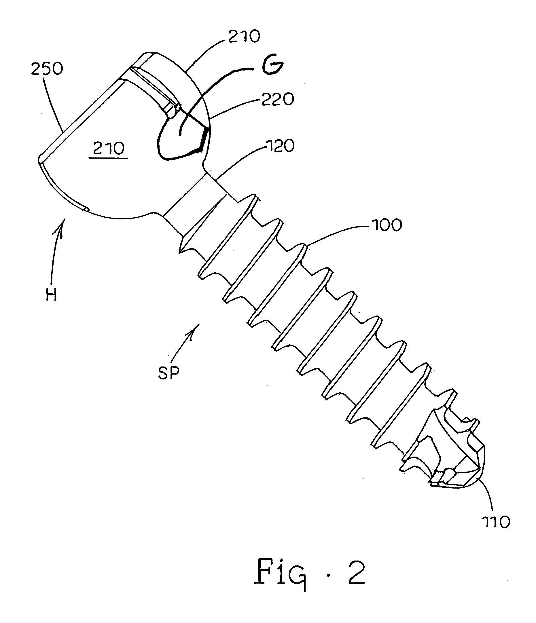
[0041] Referring now to FIGS. 1 and 2 of the drawings, fixation apparatus generally designated FA is illustrated and comprises a head portion generally designated H which can have a shank portion generally designated SP extending therefrom. An expander hub generally designated EH is shown in FIG. 1 adapted for fitting into head portion H as described later...


PUM


Abstract

Apparatuses, systems and methods for bone fixation are disclosed herein. A fixation apparatus is disclosed having a head portion having outer wall sections at least partially surrounding a central hollow area, and the head portion also having an inner bottom surface. A shank portion can extend from the head portion. An expander hub is provided for positioning at least partially within the central hollow area of the head portion and can be seated at least partially on the inner bottom surface of the head portion. The expander hub is rotatable to force the outer wall sections of the head portion outwardly for engaging and locking the fixation apparatus in place when the fixation apparatus is positioned within a hole of a plate. The fixation apparatus can advantageously be used with a plate whereby the fixation apparatus and plate can compress bone separately from locking the fixation apparatus in a desired position. Also, the angle, alignment or position of the fixation apparatus can be changed if desired even after locking of the fixation apparatus. Separate drivers can be used to drive the fixation apparatus, to rotate the expander hub to lock it in place, and to remove the fixation apparatus. The drivers can be cannulated as desired such that the drivers can be assembled in a nested and concentric configuration and can be used without removal from the nested configuration.

Description

RELATED APPLICATIONS [0001] This application claims the benefit of U.S. Provisional Patent Application Ser. No. 60 / 529,392, filed Dec. 12, 2003, the disclosure of which is incorporated herein by reference in its entirety.TECHNICAL FIELD [0002] The present subject matter relates generally to bone fixation and, more particularly to apparatuses, systems and methods for bone fixation utilizing a fixation apparatus to lock in various locked positions in order to fixate bone. BACKGROUND ART [0003] A variety of apparatuses and methods are known in the field of orthopedics for reducing, fixing and generally assisting the healing of fractured bones. In some cases, these apparatuses and methods require surgical intervention. Open reduction internal fixation (ORIF) is a developed art with respect to some portions of the body; however, many complications can exist which can prevent successful or optimal outcomes in all cases utilizing ORIF. Treatment methods can also significantly impact healin...

Claims


Application Information

Patent Timeline
IPC IPC(8): A61BA61B17/58A61B17/80A61B17/86A61B17/88B25B15/00
CPCA61B17/8038A61B17/8615B25B15/005A61B17/888A61B17/8894A61B17/8685
Inventor BALL, ROBERT J.
Owner INTEGRA LIFESCI
Learn More