Tension spring clip comprising symmetrical tension springs

Inactive Publication Date: 2005-11-10
PHOENIX CONTACT GMBH & CO KG
View PDF10 Cites 3 Cited by
  • Summary
  • Abstract
  • Description
  • Claims
  • Application Information

AI Technical Summary

Benefits of technology

[0007] It is one goal of the invention to provide a draw spring clamp by means of which switching of such cabled modules is made especially simpler and less time-consuming, and in which reset of the actuation element is achieved automatically when the actuation tool is removed.

Problems solved by technology

This achieves a positive clamping of the cabled module since release of the draw springs with the actuation tool removed is not possible.

Method used


Image

  • Tension spring clip comprising symmetrical tension springs
  • Tension spring clip comprising symmetrical tension springs
  • Tension spring clip comprising symmetrical tension springs

Examples


Embodiment Construction

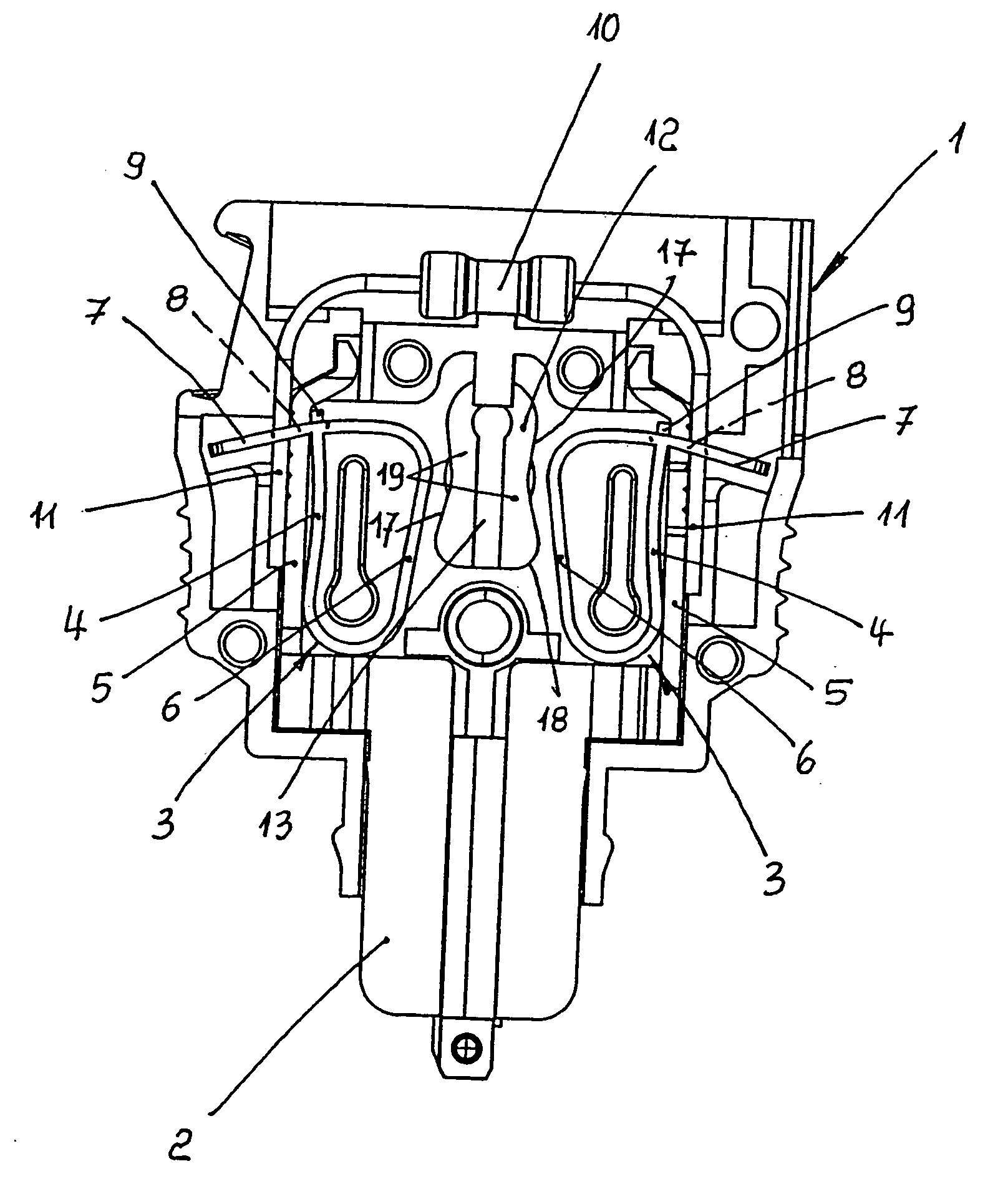
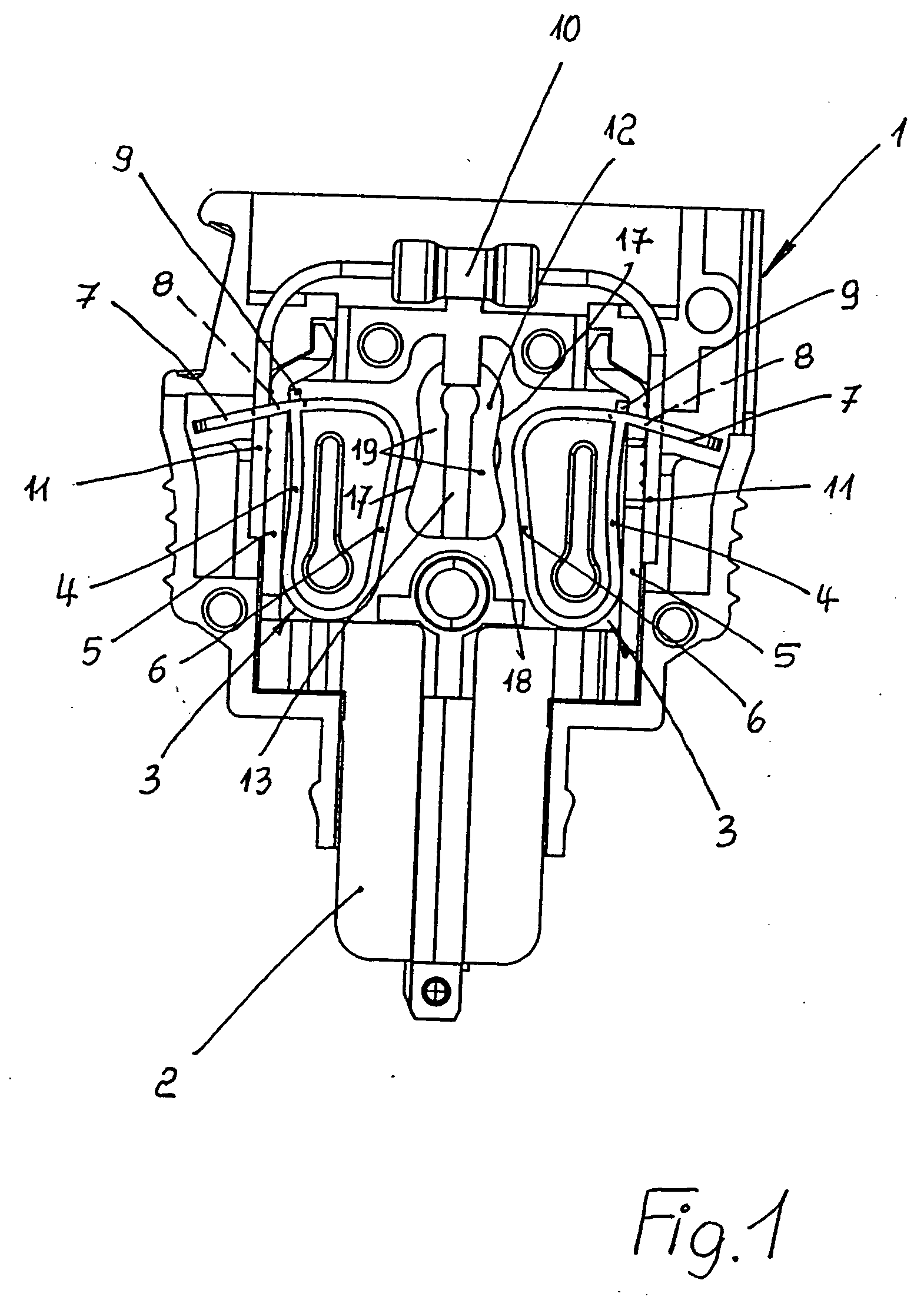
[0015] One may recognize in detail in the illustrations a clamp housing 1 on whose underside a plug element 2 is formed in order to be able to use the draw spring clamp as a plug-in module. As FIG. 1 reveals, two draw springs 3 that are positioned in mirror-image configuration. Each of these two draw springs 3 includes an attachment leg 4 that rests on a current bus 5. Made of one piece with the attachment leg 4 is a spring leg 6 that is bent into a loop along with the attachment leg 4. Thus, bent back toward the attachment leg 4, the spring leg 6 possesses a clamp leg 7 that is penetrated by a clamp window 6. The attachment leg 4 with its end 9 and the current bus 5 extend through this clamp window 8.

[0016] The two draw springs 3 provide contact for a module 10, such as an electronic component or the like, that has a cable or central region, and from which two connector cables or wires 11 correspondingly extend. Each of these wires 11 is clamped to one of the clamp positions in th...


PUM


Abstract

A draw spring clamp has loop-shaped draw springs with an attachment leg to contact a current bus and with a spring leg and clamping leg, whereby the latter is interrupted by a clamp window in order to form the clamp leg. By means of an actuation element into which a tool blade may be inserted, the spring leg of the draw springs may be loaded with tension in order to open the clamp window. This actuation element is located between the two spring legs of the draw spring that oppose each other. In order to enable time-saving actuation, the actuation element in its loaded position also rests against the two spring legs. Thus, the actuation element possesses rest positions on its opposing exteriors whose separation increases along a first direction of travel of the actuation element and decreases along the second direction.

Description

TECHNICAL FIELD [0001] The invention relates to a draw spring clamps with two draw springs positioned in mirror-image layout within a housing. BACKGROUND INFORMATION [0002] The invention relates to a draw spring clamps with two draw springs positioned in mirror-image layout within a housing. Each of these draw springs possesses an attachment leg resting on a current bus as well as a spring leg that is of one piece with it and that is bent together with the attachment leg into a loop. The attachment leg of the pertinent draw springs extends with its end and with the current bus through the clamp window. The two spring legs of the draw springs are positioned facing each other, and are loadable with tension by means of an actuation element that is positioned within a housing of the draw spring clamp into which a tool blade may be inserted for the purpose of providing spring tension along the direction toward the attachment leg when the clamp window is opened. The above-mentioned actuat...

Claims


Application Information

Patent Timeline
IPC IPC(8): H01R4/48
CPCH01R4/4845H01R4/4827H01R4/48275H01R4/48455
Inventor LANGE, OLIVER
Owner PHOENIX CONTACT GMBH & CO KG
Why Eureka
Try Eureka