
Input system, coordinate input device, and method

a technology of input system and input device, applied in the field of input system, can solve the problems of degrading the performance of each device, affecting the accuracy of the input device, and the inability to properly detect the coordinates, etc., and achieve the effect of excellent performan

Inactive Publication Date: 2005-11-10
WACOM CO LTD
View PDF3 Cites 5 Cited by
  • Summary
  • Abstract
  • Description
  • Claims
  • Application Information

AI Technical Summary

Benefits of technology

[0009] Accordingly, it is an object of the present invention to provide an input system capable of ensuring the excellent performance of each of coordinate input devices arranged and used by one user.
[0015] In the input system according to the present invention, the coordinate input device in the state, in which the position designated by the pointing device is not detected, is specified and the detection operation of the specified coordinate input device is controlled, so that the detection operation of the device which need not to detect the designated position can be interrupted, or the frequency of the detection operation or the range of the detection operation can be limited. Thus, in the use of a plurality of coordinate input devices, the operation of the coordinate input device which has to perform the detection operation can be prevented from being influenced by the detection operation of the other coordinate input device or devices which need not to perform the detection operation. According to the present invention, therefore, when a plurality of coordinate input devices are used, the performance of each coordinate input device can be prevented from degrading. Further, since the unnecessary detection operation is prevented, unnecessary power consumption can be eliminated.
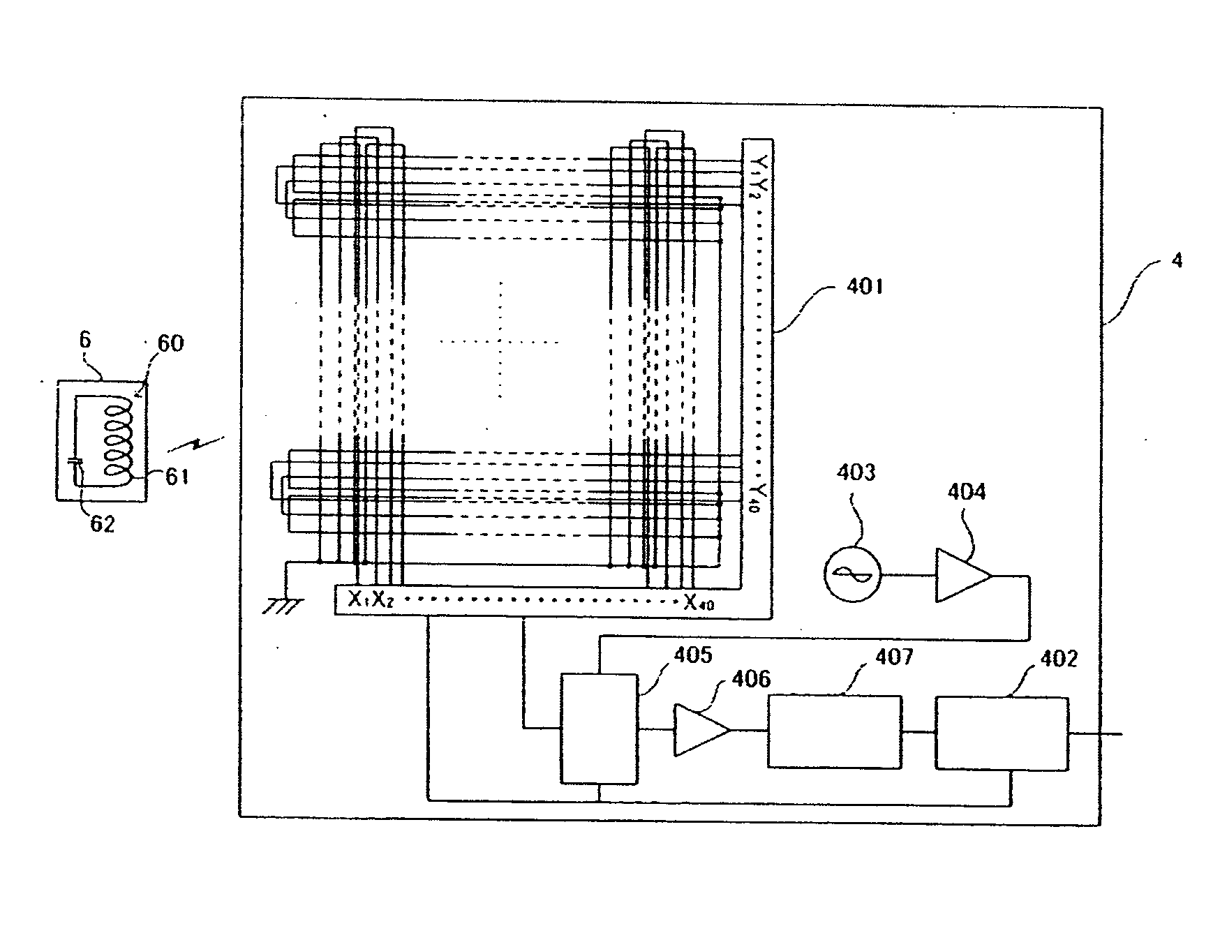
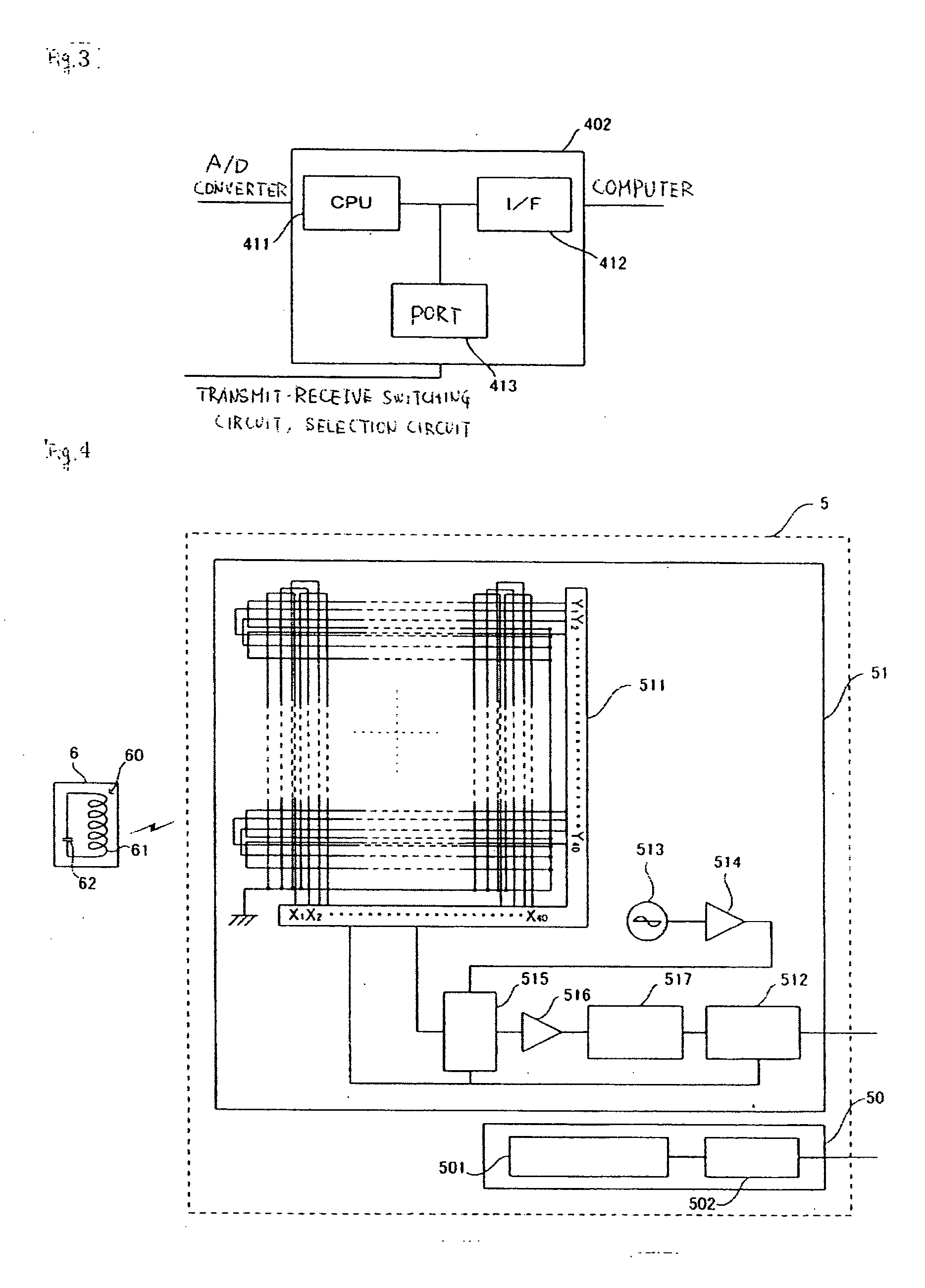
[0016] When each coordinate input device includes a plurality of loop coils and generates radio waves from the loop coils to detect the position designated by the pointing device using the radio waves, the operations of the respective coordinate input devices may probably affect each other. According to the present invention, as necessary, the detection-operation control unit included in each coordinate input device interrupts the operation for generating radio waves from the loop coils or limits the loop coils generating radio waves in the detection operation to only some of the loop coils. Thus, the detection operations of the respective coordinate input devices can be reliably prevented from affecting each other.
[0017] According to the present invention, when one of the plurality of coordinate input devices can detect the position designated by the pointing device, the other device or the other devices are specified as a coordinate input device or coordinate input devices in the state in which the position designated by the pointing device is not detected. Thus, the coordinate input device which need not to perform the detection operation can be more easily specified.
[0018] When the present invention is applied to a case where a plurality of coordinate input devices for detecting a position designated by a pointing device and generating the coordinates of the detected position are arranged and used to conduct work requiring a wide input area or work requiring various kinds of operations, the operating efficiency can be increased. For example, in executing a graphics application program through a computer, a user has to perform a drawing operation to trace a line and color an image and a setting operation to perform various settings in the drawing operation. If the user uses different coordinate input devices for the drawing operation and the setting operation, the operating efficiency can be increased. When the present invention is applied to the above example, advantageously, the performance of each coordinate input device can be prevented from degrading even in use of the coordinate input devices.

Problems solved by technology

In the case where the coordinate input devices are arranged close to each other, however, the performance of each device may be degraded.
When the coordinate input devices are arranged close to each other, therefore, the electrical or magnetic couplings between the pointing device and the respective coordinate input devices may interfere with each other.
Disadvantageously, the coordinates cannot be properly detected.
The system cannot be achieved using general-purpose tablets.

Method used


Image

  • Input system, coordinate input device, and method
  • Input system, coordinate input device, and method
  • Input system, coordinate input device, and method

Examples


Embodiment Construction

[0034] An embodiment of the present invention will now be described below with reference to the drawings.

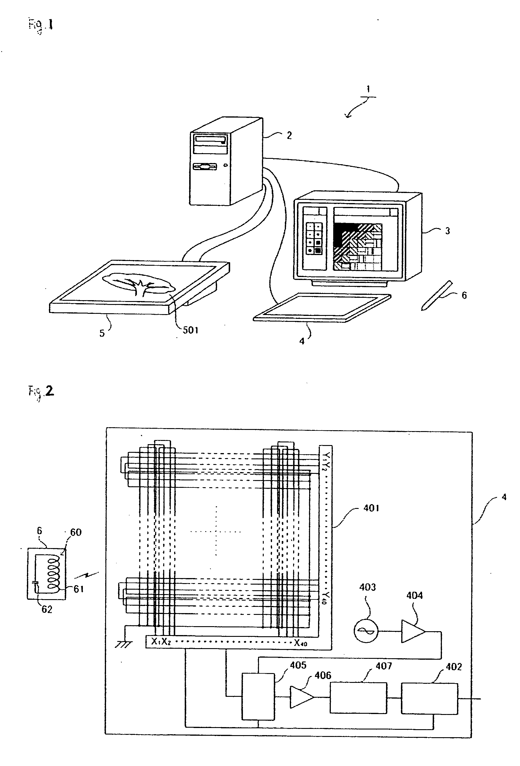
[0035]FIG. 1 schematically shows the structure of an input system 1 according to the embodiment of the present invention. Referring to FIG. 1, the input system 1 includes a computer 2, a monitor 3, a tablet 4, and a flat panel display (FPD) tablet 5.

[0036] The computer 2 is a general personal computer and is connected to the monitor 3, the tablet 4, and the FPD tablet 5.

[0037] The computer 2 executes processes based on various application programs in accordance with inputs supplied from the tablet 4 and the FPD tablet 5. The computer 2 generates display signals for various screens, e.g., an execution screen of the application program to the monitor 3 and the FPD tablet 5.

[0038] The monitor 3 includes a display screen of a cathode ray tube (CRT) or a liquid crystal display (LCD) panel and displays various screens based on display signals generated from the computer 2.

[0039] T...


PUM


Abstract

The present invention provides an input system capable of assuring the excellent performance of each of coordinate input devices arranged. A tablet and a flat panel display (FPD) tablet are connected to a computer to realize the input system. Each tablet includes loop coils and detects a position designated by an input pen using radio waves generated from the loop coils. In the input system, when the tablet can detect the position designated by the input pen, the generation of the radio waves from the loop coils of the FPD tablet is interrupted: When the FPD tablet can detect the position designated by the input pen, the generation of the radio waves from the loop coils of the tablet is interrupted.

Description

CLAIM TO PRIORITY [0001] Applicant hereby claims priority under 35 U.S.C. § 119 to Japanese Application No. 2004-094958, filed Mar. 29, 2004, the disclosure of which is incorporated herein by reference. FIELD OF THE INVENTION [0002] The present invention relates to an input system including coordinate input devices, the coordinate input device, and a program for realizing the input system. BACKGROUND OF THE INVENTION [0003] Universal Serial Bus (USB) is in widespread use as an interface standard for connecting a coordinate input device to a personal computer. In the use of the USB interface, many input devices can be easily connected to one personal computer. [0004] For example, when a plurality of well-known coordinate input devices (also called tablets) using a pen-type pointing device are arranged and used, the coordinate input devices can be used with one pointing device, resulting in excellent ease of operation. [0005] In the case where the coordinate input devices are arranged...

Claims


Application Information

Patent Timeline
Patent Type & Authority Applications(United States)
IPC IPC(8): G06F3/041G06F3/02G06F3/033G06F3/046
CPCG06F3/0227G06F3/041
Inventor CHIKAMI, TOSHIHIDE
Owner WACOM CO LTD
Learn More