Drop tube inserts and apparatus adapted for use with a riser pipe

a technology of riser pipe and drop tube, which is applied in the direction of liquid transfer device, liquid handling, packaging goods type, etc., can solve the problem of excessive amount of vapor entering the atmosphere, and achieve the effect of preventing or minimizing vapor releas

Active Publication Date: 2005-11-03
OPW FUELING COMPONENTS LLC
View PDF29 Cites 6 Cited by
  • Summary
  • Abstract
  • Description
  • Claims
  • Application Information

AI Technical Summary

Benefits of technology

[0004] Accordingly, it is an object of the present invention to obviate problems and shortcomings of conventional liquid reservoirs. More particularly, it is an ob

Problems solved by technology

Such configurations have proven to be very effective, however, the interstitial space between the riser pipe and the drop tube can allow an excessive amount of vapor to be introduced into the atmosphere, especially during the filling process

Method used


Image

  • Drop tube inserts and apparatus adapted for use with a riser pipe
  • Drop tube inserts and apparatus adapted for use with a riser pipe
  • Drop tube inserts and apparatus adapted for use with a riser pipe

Examples


Embodiment Construction

[0020] Reference will now be made in detail to various exemplary embodiments of the invention, concepts of which are illustrated in the accompanying drawings, wherein like numerals indicate the same elements throughout the views.

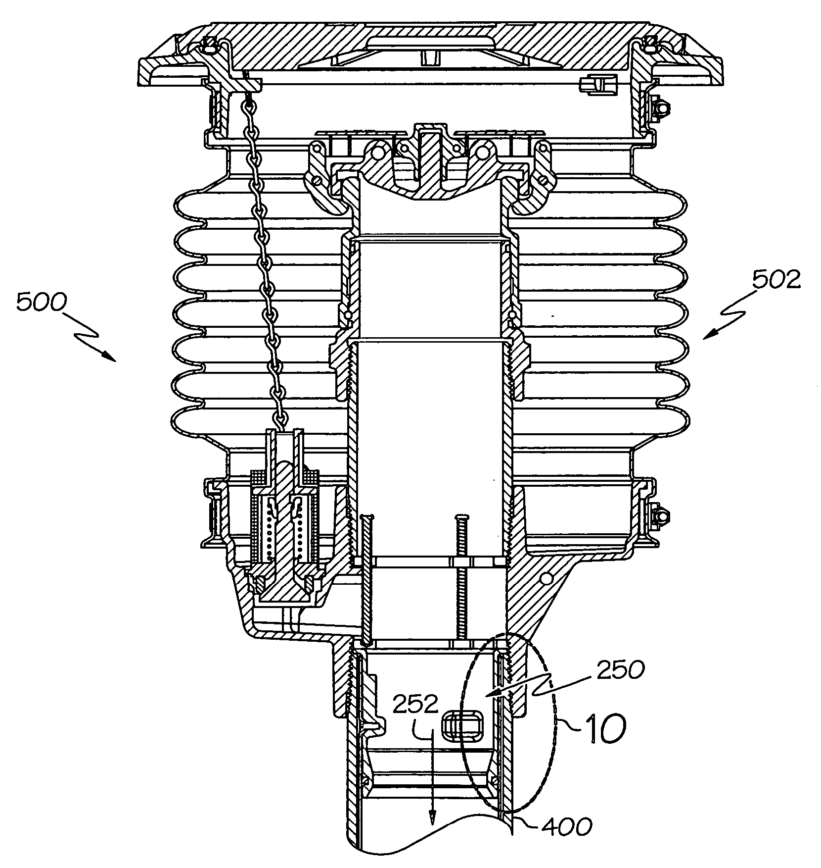
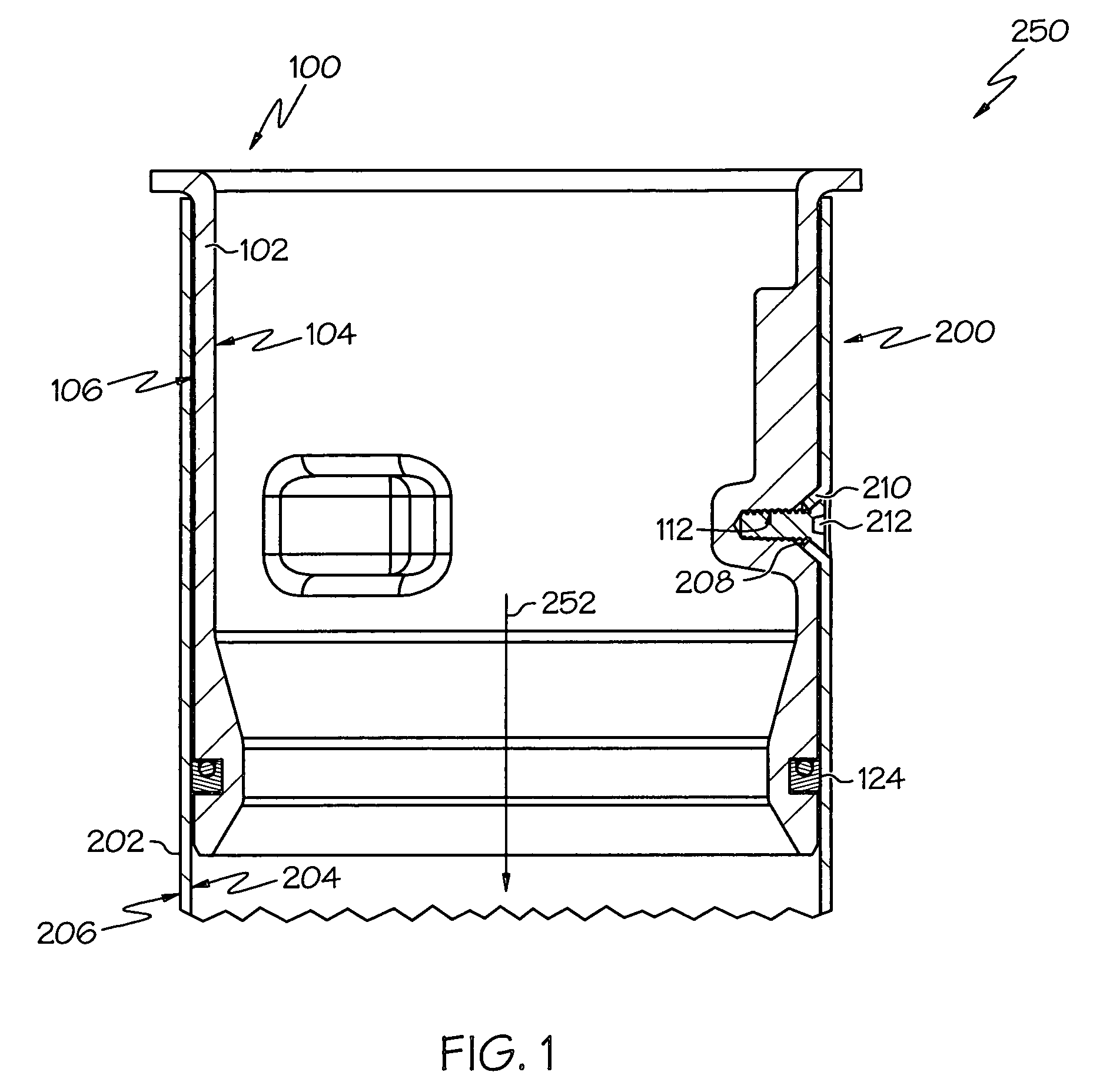
[0021]FIG. 1 depicts an exemplary apparatus 250 for use with a riser pipe of a liquid reservoir, such as a liquid storage tank. As shown, the apparatus 250 includes a drop tube 200 adapted for at least partial disposition in a riser pipe 400 (see FIG. 9) of a liquid reservoir. The drop tube 200 includes a wall 202 with an inner surface 204 and an outer surface 206. The wall 202 can take many shapes in accordance with the concepts of the present invention. For example, the wall 202 can include circular and / or noncircular cross sectional shapes. In particular examples, and as shown in the drawings, the wall may comprise a cylinder with a cylindrical wall wherein the inner surface 204 comprises an inner cylindrical surface and the outer surface 206 comprises a...


PUM

PropertyMeasurementUnit
Areaaaaaaaaaaa

Abstract

Drop tube inserts and apparatus adapted for use with a riser pipe of a liquid reservoir are provided. Apparatus include a drop tube insert at least partially disposed within an end portion of a drop tube. The drop tube insert includes a wall with inner and outer surfaces wherein the wall of the drop tube insert is devoid of any opening extending between its inner and outer surfaces.

Description

TECHNICAL FIELD [0001] The present invention relates generally drop tube inserts and apparatus, and more specifically to drop tube inserts and apparatus adapted for use with a riser pipe of a liquid reservoir. BACKGROUND OF THE INVENTION [0002] Our increasingly mobile and mechanized society uses a variety of different fuels (e.g., gasoline, diesel fuel, ethanol, etc.) as energy. Liquid fuels are generally stored in liquid reservoirs such as underground storage tanks, above ground tanks, or any of a variety of different containers. Typically, liquid fuel reservoirs have inlets and outlets through which fuel can be added to and / or removed from the reservoir. These inlets and outlets may typically consist of a riser pipe extending from the reservoir. Internal to the riser pipe is a drop tube and the space between the riser pipe and the drop tube is frequently referred to as the interstitial space between the riser pipe and the drop tube. The riser pipe is typically threaded to an adapt...

Claims


Application Information

Patent Timeline
IPC IPC(8): B67D7/32B65D90/00B67D7/78F16L25/08
CPCB65D90/00F16L25/08B67D7/78B67D7/3209B65D90/26B65D90/28
Inventor PENDLETON, DAVID R.KESTERMAN, JAMES E.KANE, KRISTOPHER A.
Owner OPW FUELING COMPONENTS LLC
Why Eureka
Try Eureka