
Storage device enclosure

a storage device and enclosure technology, applied in the direction of machine supports, electric apparatus casings/cabinets/drawers, instruments, etc., can solve the problems of servo errors, write inhibitions, disk drive operation, etc., to reduce manufacturing costs, maintain structural rigidity, and reduce disk drive vibration transmissions

Inactive Publication Date: 2005-10-27
GLOBALFOUNDRIES INC
View PDF22 Cites 24 Cited by
  • Summary
  • Abstract
  • Description
  • Claims
  • Application Information

AI Technical Summary

Benefits of technology

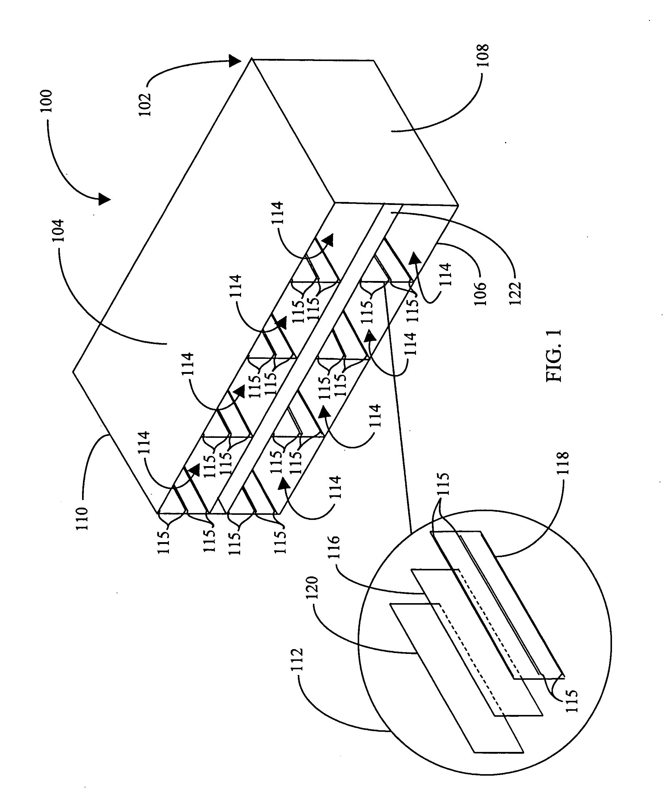
[0013] The present invention has been developed in response to the present state of the art, and in particular, in response to the problems and needs in the art that have not yet been fully solved by currently available enclosures for storage devices. Accordingly, the present invention has been developed to provide an improved enclosure chassis with damped elements configured to curtail disk drive vibration transmissions while maintaining structural rigidity. The present invention also decreases manufacturing costs by using clip-on damped springs to dampen vibration and keyed bezel positions to prevent damage to the interface connection in the enclosure and in the disk drive, thus overcoming many or all of the above-discussed shortcomings in the art.
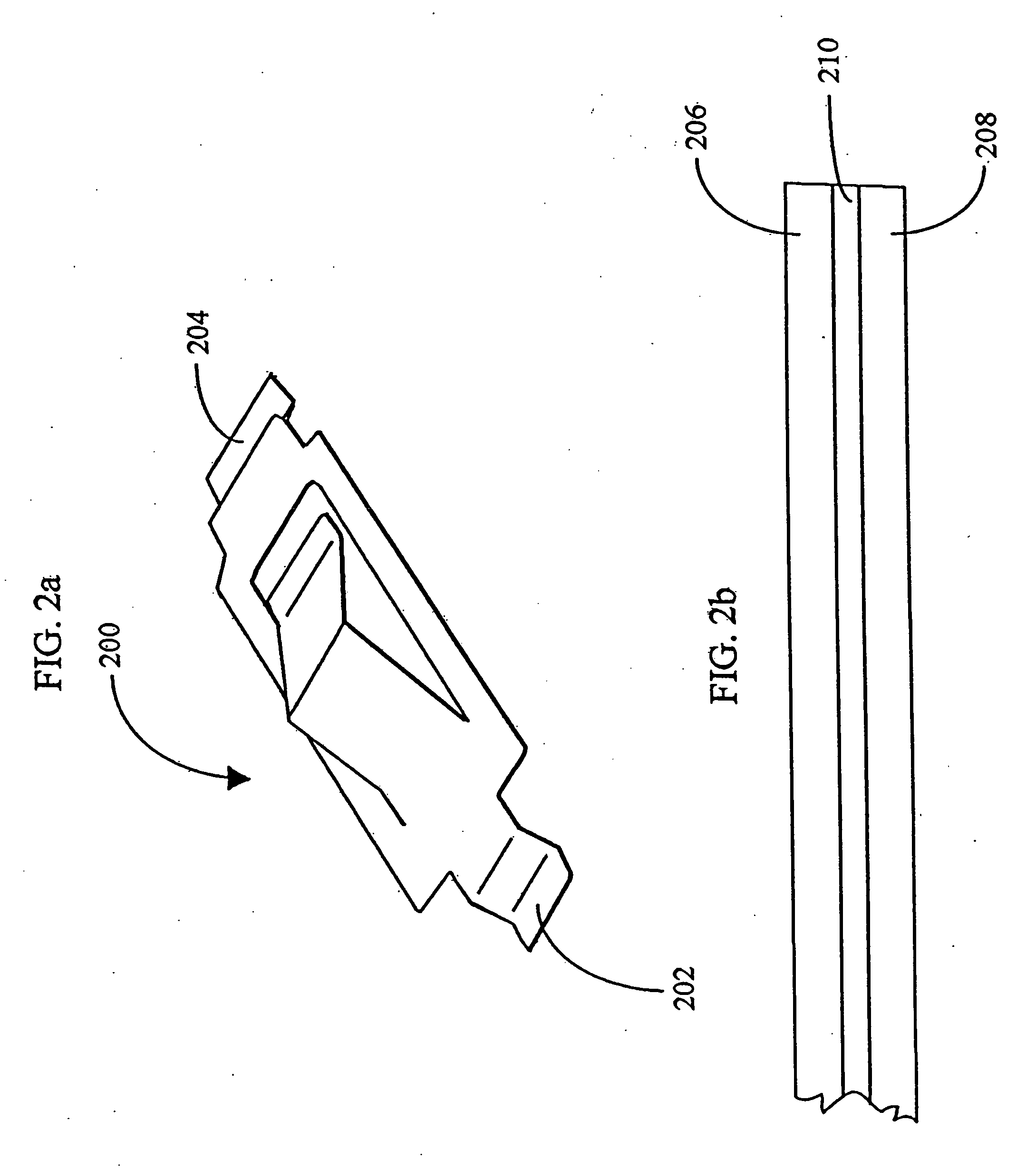
[0014] The present invention solves many or all of the above-described problems by providing an improved enclosure for storage devices. An enclosure chassis stores at least one disk drive, storage device, hard disk drive, or nonvolatile storage device, and includes at least one mounting surface having a viscoelastic layer disposed between a first layer and a second layer to reduce vibration propagation throughout the mounting surface(s). A receiver, secured to the mounting surface within the enclosure chassis and configured to receive a storage device carrier retaining a disk drive, positions the storage device carrier to the mounting surface(s). Clip-on damped springs are coupled to the storage device carrier for guiding the storage device carrier through the receiver and for coupling the storage device carrier to the mounting surface(s). A bezel of the storage device carrier is configured to receive a key in one of a plurality of key positions, with each key position corresponding to a particular disk drive / enclosure chassis interface.
[0015] The damped enclosure chassis according to the invention overcomes problems caused by self-induced vibration and problems caused by vibrations transmitted from other disk drives stored in the enclosure chassis. A further advantage of using a damped enclosure chassis according to the invention is that the vibration transmission problems have been overcome, whereby functioning drives should no longer be replaced unnecessarily.
[0016] The clip-on damped springs according to the invention reduce part count, reduce manufacturing processes, and reduce time in manufacturing.
[0017] An advantage of the keying elements is that it eliminates enclosure / disk drive interface connection damage resulting from attempts to connect incompatible interface connections.

Problems solved by technology

Whether the disk drives are mounted vertically or horizontally, a problem arises with regard to the operation of disk drives when mounted next to each other.
The problem occurs during seek movements of the actuator across the disk.
The rotational energy created by a disk drive actuator is often sufficient to move the body of the disk drive and create servo errors.
Such movement can result in write inhibits, soft errors, and slow response time, generally characterized as self-induced problems.
In addition, when the disk stack is out of balance, the rotating disks cause vibration in the drive.
This vibration transmission may result in write inhibits, soft errors, and slow response from the disk drives, generally characterized as vibration transmission problems.
Further, when the systems using the disk drives indicate problems generally attributable to damaged disk drives, the disk drive may be replaced, when in reality the disk drive is not damaged, rather vibration transmissions resulting from am enclosure chassis having insufficient stiffness and damping may be causing the problems.
As more tracks are written per inch on disk drives, the severity of the problems will increase as the read / write head makes increased movement across the disks.
Additionally, the method of securing the springs to the disk storage device carriers is often time consuming and costly due to additional components and manufacturing processes.
Consequently, it is not uncommon for a disk drive or an enclosure chassis to be damaged when a disk drive with an incompatible interface is placed in an enclosure chassis.
For example, when a disk drive having an FC interface is positioned into a enclosure chassis configured to receive a disk drive with an SCSI interface, either the disk drive interface is damaged, the enclosure chassis connection is damaged, or both are damaged.
The solution to one problem, however, may counteract attempts to solve the other problem, or even aggravate the other problem.

Method used


Image

  • Storage device enclosure
  • Storage device enclosure
  • Storage device enclosure

Examples


Embodiment Construction

[0029] For the purposes of promoting an understanding of the principles of the invention, reference will now be made to the exemplary embodiments illustrated in the drawings, and specific language will be used to describe the same. It will nevertheless be understood that no limitation of the scope of the invention is thereby intended. Any alterations and further modifications of the inventive features illustrated herein, and any additional applications of the principles of the invention as illustrated herein, which would occur to one skilled in the relevant art and having possession of this disclosure, are to be considered within the scope of the invention.

[0030] Reference throughout this specification to “one embodiment,”“an embodiment,” or similar language means that a particular feature, structure, or characteristic described in connection with the embodiment is included in at least one embodiment of the present invention. Thus, appearances of the phrases “in one embodiment,”“in...


PUM


Abstract

An enclosure for storage devices having at least one mounting surface and a viscoelastic layer disposed between a first layer and a second layer of the mounting surface. A receiver secured to the mounting surface within the enclosure receives a storage device carrier that retains a disk drive and positions the storage device carrier within the enclosure. Clip-on damped springs, coupled to the storage device carrier, guide the storage device carrier through the receiver and couple the storage device carrier to the mounting surface(s). A bezel of the storage device carrier is configured to receive a key in one of a plurality of key positions, with each key position corresponding to a particular disk drive / enclosure chassis interface.

Description

BACKGROUND OF THE INVENTION [0001] 1. Field of the Invention [0002] This invention relates in general to enclosures for storage devices. Specifically, the present invention relates to enclosures with vibrational damping capabilities for receiving disk drive storage devices. [0003] 2. Description of the Related Art [0004] In conventional disk drives, the data storage disk is mounted on a main body of the disk drive and is typically either mounted horizontally for rotation about a vertical axis or is mounted vertically for rotation about a horizontal axis. The disk head, which may be a read-only head or a read-and-write head is movably mounted on the main body of the disk drive in order to track across the disk to desired locations where data needs to be read or written. Such operations are known as “seek operations.” Although in some circumstances the disk drive may be permanently and rigidly fixed to the enclosure chassis, it often occurs that the disk drive must be mounted so as to...

Claims


Application Information

Patent Timeline
IPC IPC(8): G06F1/16G11B33/08G11B33/12
CPCG11B33/128G11B33/08
Inventor CONNELLY, DONALD M. JR.GREEN, KENTON COLEMANLEW, DAVID TUNGSCHNEEBELI, KENNETH ROBERTURBISCI, PETER PAUL
Owner GLOBALFOUNDRIES INC
Learn More