
Method of selecting ions in an ion storage device

a technology of ion storage and ion selection, which is applied in the direction of beam deviation/focusing, separation process, instruments, etc., can solve the problems of uncontrollable oscillation and loss of ion storage space, and achieve the effect of shortening the ion selection time and simplifying the control of the ion selecting wav

Active Publication Date: 2005-10-27
SHIMADZU CORP
View PDF8 Cites 14 Cited by
  • Summary
  • Abstract
  • Description
  • Claims
  • Application Information

AI Technical Summary

Benefits of technology

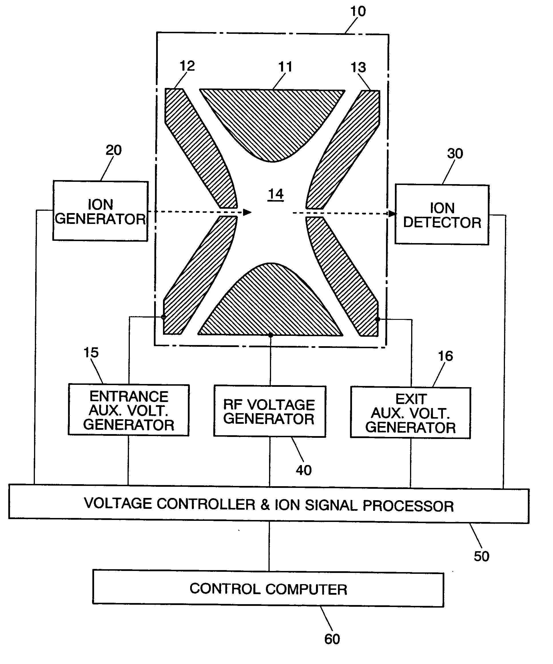
The present invention provides a method for selecting ions in an ion storage device by applying an ion selecting electric field. The method simplifies the control of the ion selecting waves and their adjustment, and shortens the ion selecting time. The ion selecting electric field is generated by a base wave and a continuously changing amplitude pattern. The method includes a wave storage for storing a unit wave, a base wave generator for generating a base wave, an amplitude wave generator for generating a continuously changing amplitude pattern, and a multiplier for multiplying the base wave and the amplitude pattern. The intensity of the ion selecting electric field increases with time, resulting in the selection of ions with desired mass to charge ratios at a high resolution. The control of the ion selecting waves is simplified and the ion selecting time is shortened compared to previous methods.

Problems solved by technology

In the meantime, such ions collide with the electrodes surrounding the ion storage space or escape from the opening (holes) of the electrodes, so that they are lost from the ion storage space.
But ions having the characteristic frequency at either end of the notch oscillate uncontrollably, so that some of the ions are ejected and some remain in the ion storage space depending on the intensity of the electric field.

Method used


Image

  • Method of selecting ions in an ion storage device
  • Method of selecting ions in an ion storage device
  • Method of selecting ions in an ion storage device

Examples


Embodiment Construction

[0026] An ion selecting method embodying the present invention is described. The method uses an ion trap for storing ions and adopts an FNF wave as the constant pattern unit wave.

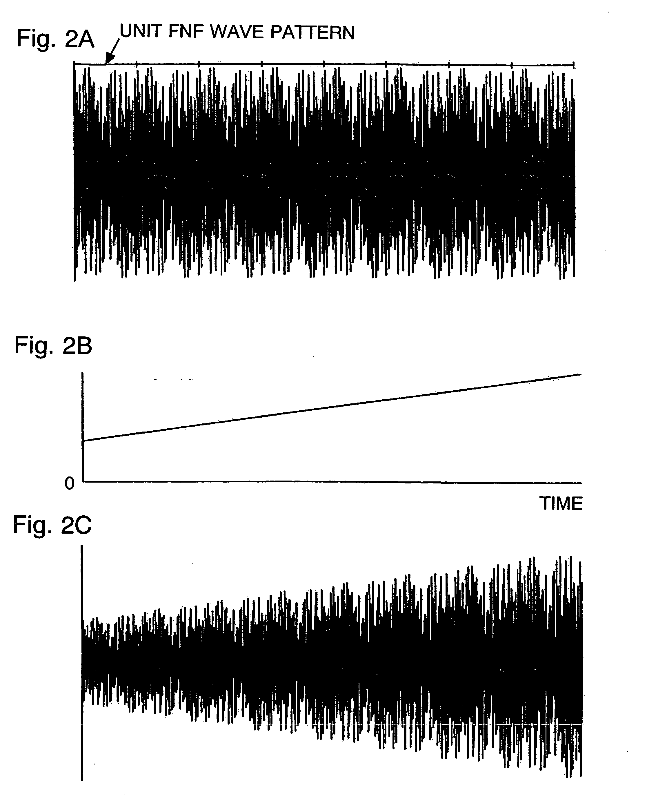
[0027]FIG. 1 shows an example of an FNF wave composed of 200 sinusoidal waves of different frequencies. In conventional ion storage devices, the amplitude of the FNF waves or SWIFT waves is controlled to have an appropriate amplitude according to the mass to charge ratio of the ions to be selected. But the amplitude is not changed in a unit wave. In the present invention, the ion selecting wave is generated as follows. First, as shown in FIG. 2A, the unit FNF wave of FIG. 1 is repeated to form a succession base wave. The succession base wave is then multiplied by the continuously changing amplitude pattern as shown in FIG. 2B to generate the wave as shown in FIG. 2C, in which the amplitude changes as time passes.

[0028] In the actual device, the wave as shown in FIG. 2C is not directly generated, but produ...


PUM


Abstract

The method of the present invention is to select ions having a predetermined mass to charge ratio by applying an ion selecting electric field in an ion storage space of an ion storage device. The method is characterized in that the ion selecting electric field is generated to be proportional to a product of a) a base wave composed of a repetition of a unit wave of a constant amplitude and a predetermined pattern, and b) an amplitude pattern which changes continuously. The amplitude pattern is preferred to increase as time passes in order to gradually increase the intensity of the ion selecting electric field applied to the ion storage space until ions of a desired mass to charge ratio are selected. The unit wave may be generated by the FNF method or by the SWIFT method. Further, it is effective to increase the intensity of the frequency components of the unit wave as the frequency is farther from the characteristic frequency of the object ion having a desired mass to charge ratio.

Description

[0001] The present invention relates to a method of selecting object ions quickly at high resolution in an ion storage device. BACKGROUND OF THE INVENTION [0002] In an analyzer using an ion storage device, such as, for example, a Fourier Transformation Ion Cyclotron Resonance (FTICR) apparatus or an ion trap mass spectrometer, ions are isolated (or selected) as follows. While ions are stored in an ion storage space, an appropriate electric field is applied to the ion storage space, whereby ions having certain mass to charge ratios (m / e) are selectively ejected. Such a method that enables selection of ions while they are stored in the storage space allows the use of an advanced mass analysis called tandem mass spectrometry (MS / MS). [0003] In the MS / MS analysis, ions of various mass to charge ratios are given from an ion generator to an ion storage space. When a certain selecting electric field is applied to the ion storage space, only ions of a specific mass to charge ratio remain in...

Claims


Application Information

Patent Timeline
Patent Type & Authority Applications(United States)
IPC IPC(8): H01J3/14H01J49/00H01J37/05H01J49/42
CPCH01J49/427
Inventor KAWATO, EIZO
Owner SHIMADZU CORP
Learn More