
Bending device

Inactive Publication Date: 2005-10-27
OPTON CO LTD
View PDF5 Cites 13 Cited by
  • Summary
  • Abstract
  • Description
  • Claims
  • Application Information

AI Technical Summary

Benefits of technology

[0004] However, in a conventional bending device as above, the right and left bending jigs are moved to the positions corresponding to the respective centers for bending depending on the bending direction. Therefore, large and heavy left and right jigs provided with the respective bending and clamping dies have to be moved in its entirety, thus making the device complex and huge.
[0005] One object of the present invention is to provide a bending device which is simple in structure and capable of bending a longitudinal workpiece to both the left and right sides.
[0009] Consequently, the present invention enables bending of the workpiece to both the left and right sides, using a single pair of the bending die and the clamping die. Thus, the configuration of the device can be simple.

Problems solved by technology

Therefore, large and heavy left and right jigs provided with the respective bending and clamping dies have to be moved in its entirety, thus making the device complex and huge.

Method used


Image

  • Bending device
  • Bending device
  • Bending device

Examples


Embodiment Construction

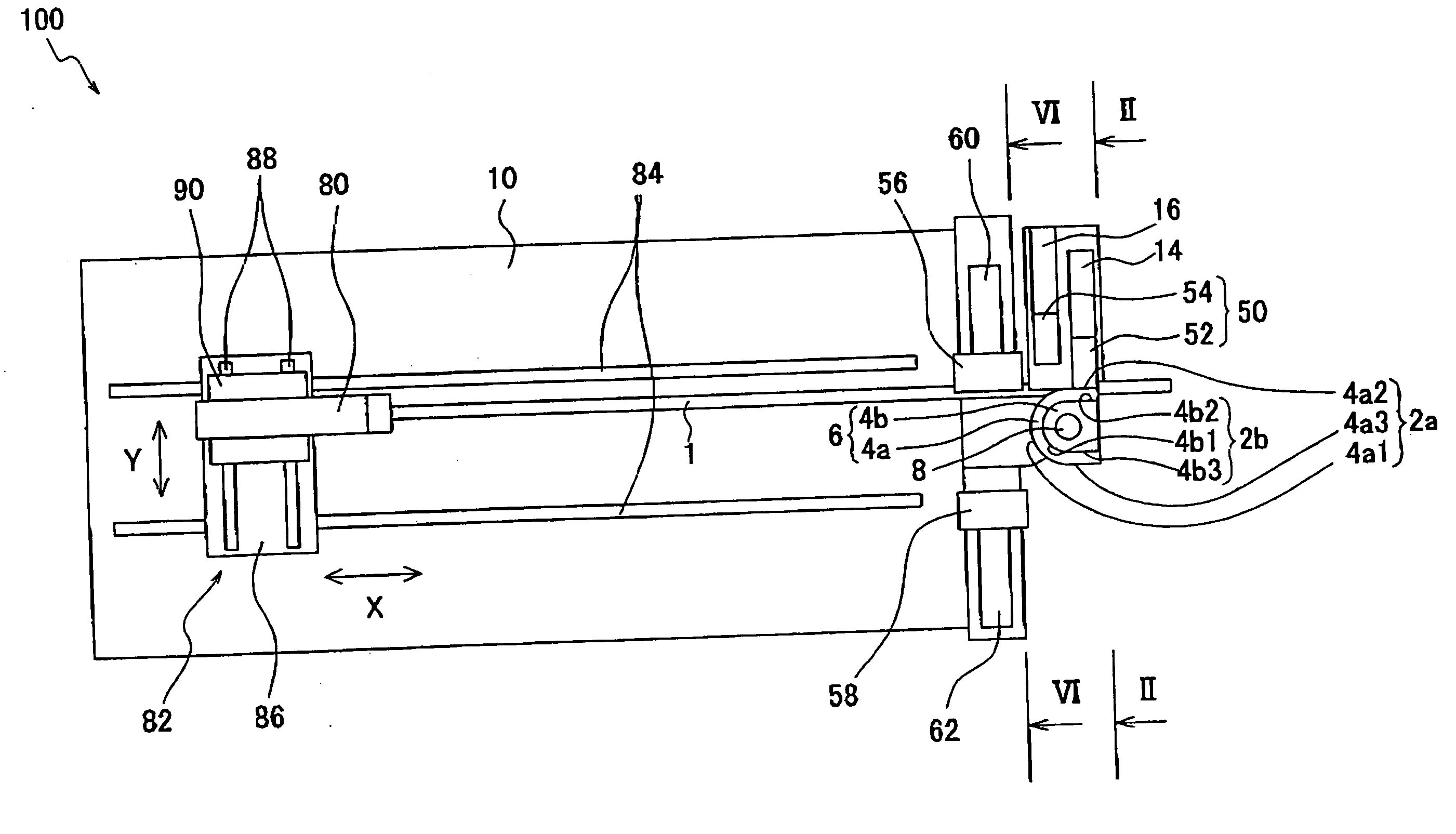
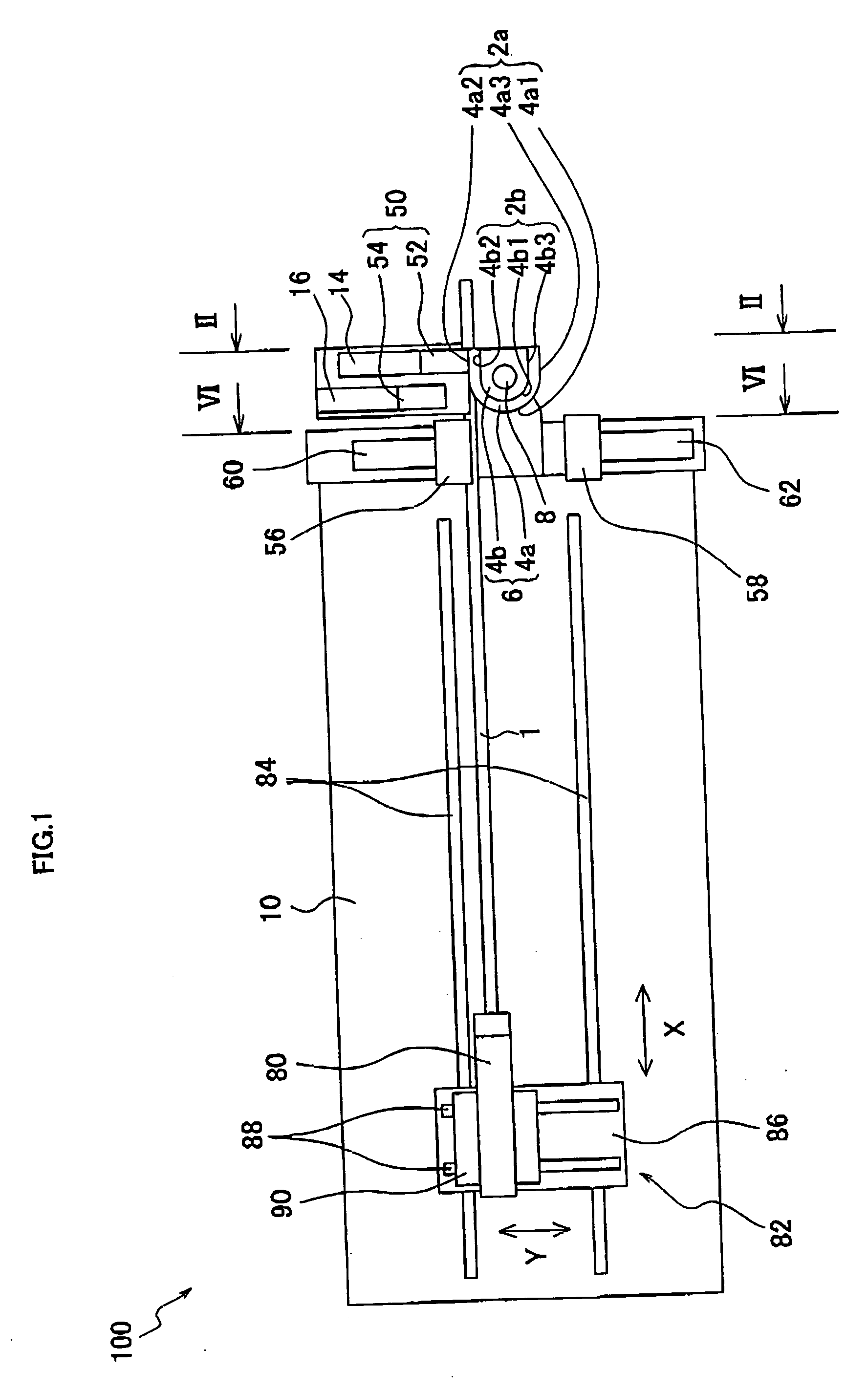
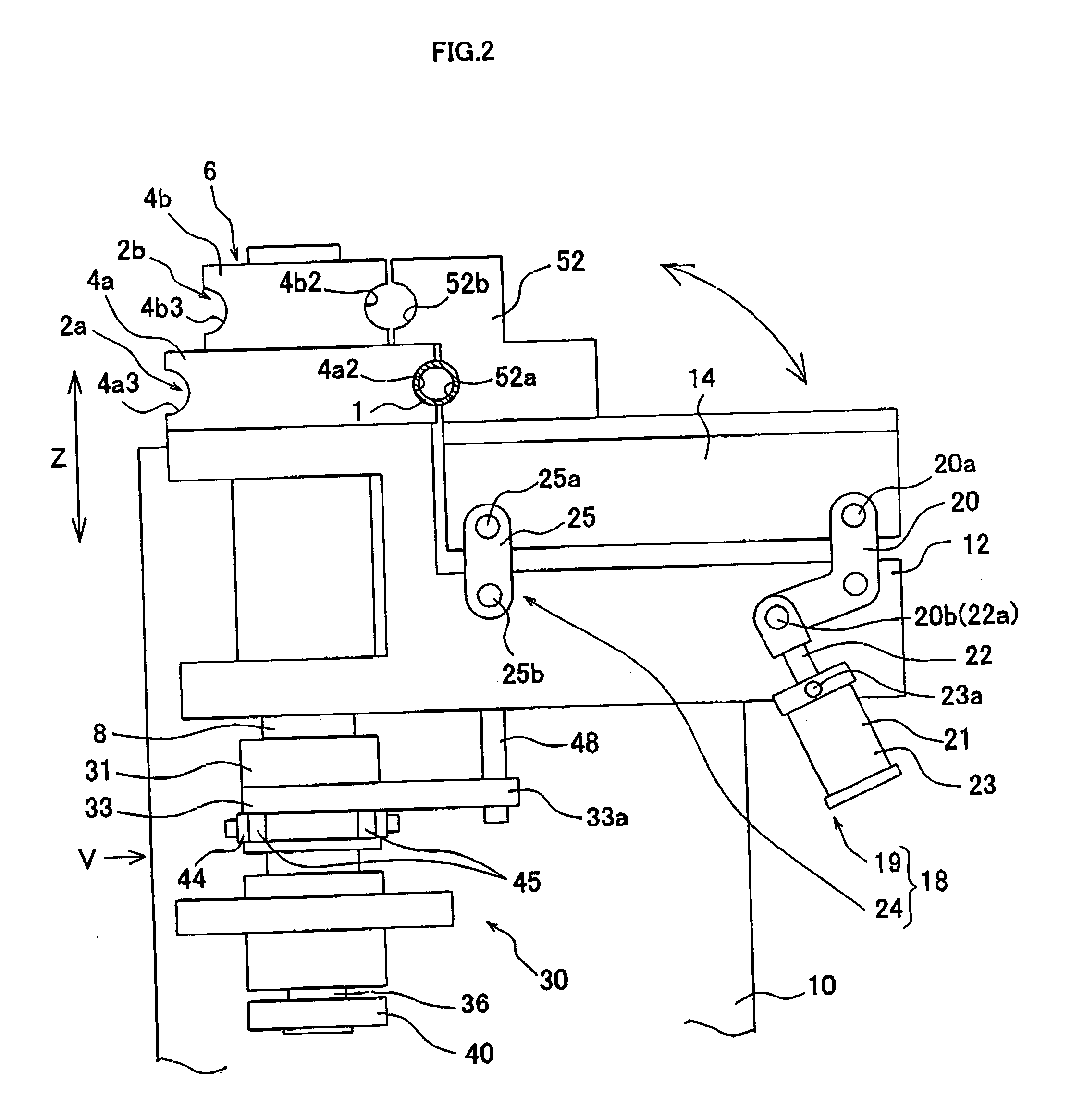
[0056] As shown in FIGS. 1 to 4, a bending device 100 of the present embodiment comprises a bending die 6, a clamping die 50, a right pressure die 56, a left pressure die 58, and a chuck 80. The clamping die 50 includes a clamping die 52 for right bend and a clamping die 54 for left bend.

[0057] As later explained, the bending device 100 bends a workpiece 1, such as a longitudinal pipe, to the right side (i.e., a direction of arrow R in FIG. 9A), by cooperation between the bending die 6, the clamping die 52 for right bend, and the right pressure die 56. Also, the bending device 100 bends the workpiece 1 to the left side (i.e., a direction of arrow L in FIG. 10A), by cooperation between the bending die 6, the claming die 54 for left bend, and the left pressure die 58.

[0058] The bending die 6 is provided in its outer shape with a plurality of bending grooves 2a, 2b (see FIGS. 2 and 4) in tiers, as a plurality of bending die contact portions corresponding to a plurality of bending sha...


PUM

PropertyMeasurementUnit
Forceaaaaaaaaaa

Abstract

The bending device is adapted to bending of a longitudinal workpiece. The device comprises a bending die that has an outer shape corresponding to the bending shape, a clamping die that clamps the workpiece with the bending die, and a rotation mechanism that rotates the bending die and the clamping die to a predetermined bending direction while the workpiece is being clamped between the bending die and the clamping die. The rotation mechanism is provided with a selection mechanism that allows switching between a first rotation mode in which the bending die and the clamping die are rotated in a body and a second rotation mode in which one of the bending die and the clamping die is rotated independently of the other die.

Description

FIELD OF THE INVENTION [0001] This invention relates to a bending device, which bends a longitudinal workpiece to both left and right sides. BACKGROUND OF THE INVENTION [0002] As disclosed in the Unexamined Japanese Patent Publication No. 62-267024, a conventionally known bending device, which bends a longitudinal workpiece to both left and right sides, is provided with a right bending jig, including a pressure die, a bending die, and a clamping die, to be used in bending the workpiece to a right side, and a left bending jig, including a pressure die, a bending die, and a clamping die, to be used in bending the workpiece to a left side. [0003] When bending the workpiece to the right side, the right bending jig is moved to the position corresponding to the center of right bending of the workpiece so as to execute right bending. When bending the workpiece to the left side, the left bending jig is moved to the position corresponding to the center of left bending of the workpiece so as ...

Claims


Application Information

Patent Timeline
IPC IPC(8): B21D7/02B21D7/024B21D7/025B21D11/07
CPCB21D7/021B21D11/07B21D7/024E01F7/04E04H17/16E04H17/20
Inventor YOGO, TERUAKI
Owner OPTON CO LTD
Learn More