
Truss manufacturing method and system

a manufacturing method and a technology for trusses, applied in the direction of girders, joists, buildings, etc., can solve the problems of less efficient in terms of stud material, less efficient in terms of span and load capacity of frame trusses, and more difficult design and assembly of back-to-back trusses

Inactive Publication Date: 2005-10-20
KARDOSZ TIMOTHY J +1
View PDF8 Cites 33 Cited by
  • Summary
  • Abstract
  • Description
  • Claims
  • Application Information

AI Technical Summary

Benefits of technology

[0007] A kit is also provided for making a truss. In one embodiment, such a kit includes one or more chord members and one or more web members. The one or more chord members are formed using structural studs that each have a web portion. Similarly, the one or more web members are formed using structural studs that each have a web portion. The chord and web members also each have an alignment guide located on their web portions where they are to connect with another chord or web member thereby enabling the truss to be assembled without the need for a jig.

Problems solved by technology

One drawback, however, is that frame trusses are limited in their span and load capabilities and are less efficient in terms of the amount of stud material needed within each truss for supporting a given load.
Unfortunately, however, such back-to-back trusses are more difficult to design and assemble because of their more complicated web member configurations.
As with frame and other metal trusses, roll-form machines can be used to efficiently generate the stud members used for the back-to-back trusses, but assembling the members into the trusses is more difficult, especially when different truss types are being assembled.
Unfortunately, when trusses of many different designs are to be made, this method breaks down because an excessive amount of time is required for creating a separate jig for each different truss design.

Method used


Image

  • Truss manufacturing method and system
  • Truss manufacturing method and system
  • Truss manufacturing method and system

Examples


Embodiment Construction

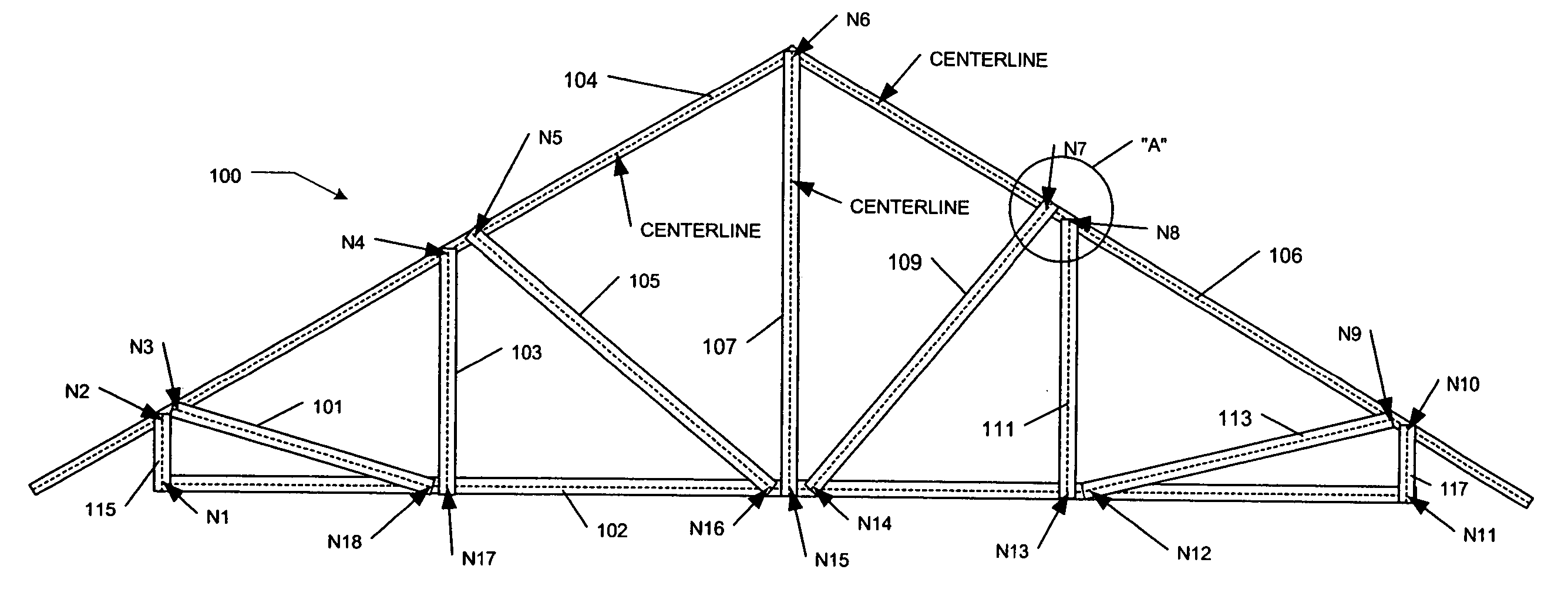
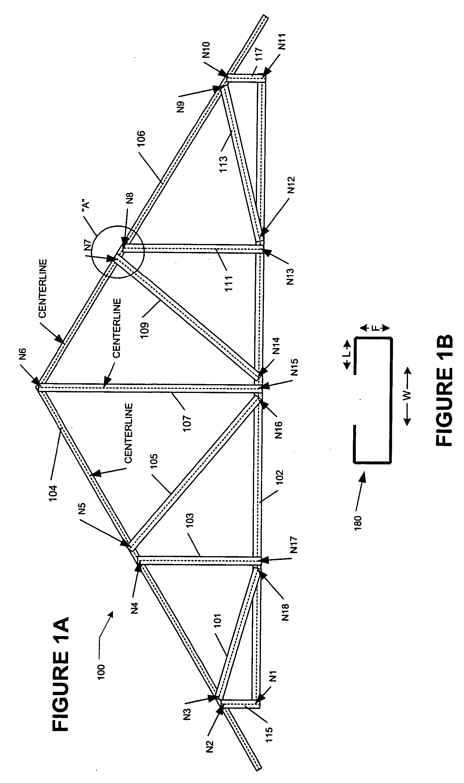
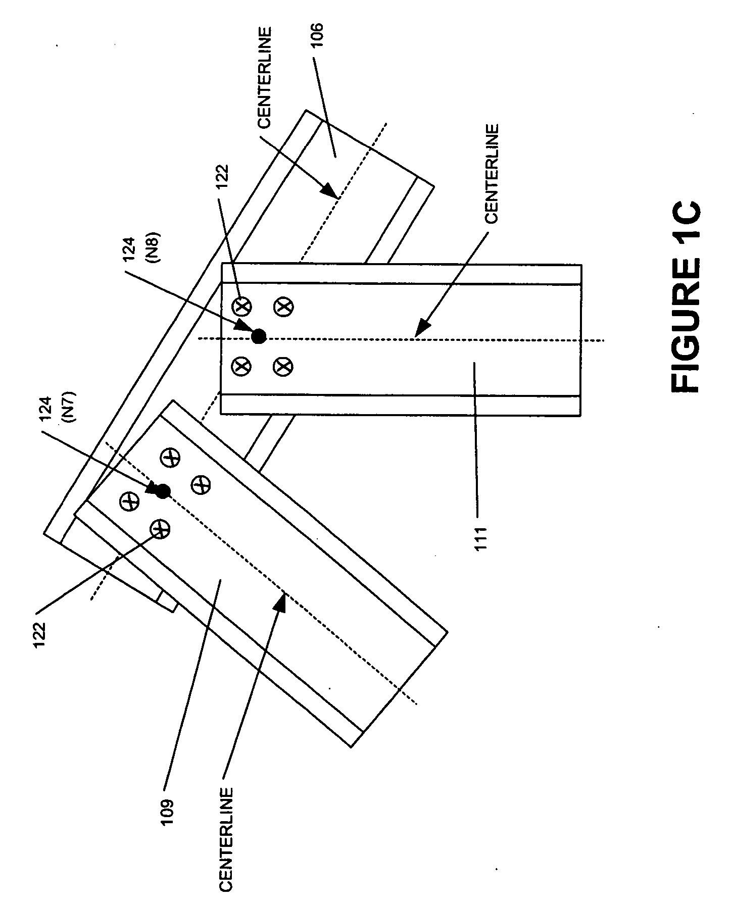
[0016] With reference to FIGS. 1A-1C, an exemplary roofing truss 100 made in accordance with an embodiment of the present invention is shown. Truss 100 is a conventional roof truss made from roll-formed, structural stud members connected in a back-to-back configuration. It generally comprises a lower C-channel chord member 102, upper C-channel chord members 104, 106, and C-channel web members 101 to 117. The centerlines for each member are shown, along with connection nodes N1 to N18.

[0017] Truss 100 is a conventional roof truss formed, e.g., from light gauge (22 to 12 .ga) steel stud members, but it is formed using techniques of the present invention and takes advantage of features available on conventional roll-forming machines. Namely, the machine is used not only to form and cut each truss member into its proper dimensions, but also, it applies an alignment guide at each part of a member that is connected to another member. An alignment guide, as used herein, can be anything su...


PUM


Abstract

Methods and systems are provided for making one or more structural stud trusses without the need for using a jig when the truss is assembled. In one embodiment, data identifying a plurality of structural stud members for making the truss is generated. The data includes data for each stud including physical stud parameters and one or more locations for an alignment guide where another member is to connect with it. A roll forming machine is controlled with the generated data to produce the plurality of stud members whereby the roll forming machine applies one or more alignment guides onto each member based on locations identified in the generated data. Finally, after all or some of the stud members are formed, the members are assembled to form the truss using the alignment guides to align connecting members with each other in order to fasten them together.

Description

TECHNICAL FIELD OF THE INVENTION [0001] The present invention generally relates to methods and systems for making trusses. In particular, it relates to a method and system for making trusses out of metal members without the need for using an alignment jig. BACKGROUND OF THE INVENTION [0002] Metal trusses are used for both commercial and residential structures. They are typically formed either from structural stud members or a combination of structural stud, non-structural stud and track members. Structural studs have cross-sectional profiles that provide them with structural stability; tracks generally have “U” shaped profiles that allow them to receive stud members fixed in a conventional. perpendicular configuration for making frame sections; and non-structural studs have profiles that give them reduced structural support but make them amenable for other functions such as receiving other studs. [0003] Different design types such as frame and back-to-back trusses are commonly used ...

Claims


Application Information

Patent Timeline
IPC IPC(8): E04B1/32E04C3/11
CPCE04C3/11
Inventor KARDOSZ, TIMOTHY J.ZUNIGA, MARTIN J.
Owner KARDOSZ TIMOTHY J
Learn More