
Semiconductor light emitting devices including a luminescent conversion element and methods for packaging the same

a technology of semiconductor light emitting devices and luminescent conversion elements, which is applied in the direction of semiconductor devices, solid-state devices, sweetmeats, etc., can solve the problems of lens not floating, movement, and may be referred to as squeeze-out,

Active Publication Date: 2005-10-06
CREELED INC
View PDF57 Cites 195 Cited by
  • Summary
  • Abstract
  • Description
  • Claims
  • Application Information

AI Technical Summary

Benefits of technology

[0020] In other embodiments of the present invention, the device has a minimum color temperature no more than 30 percent below a maximum color temperature thereof over a 180 (+ / −90 from central axis)-degree range of emission angles. The device may have a primary emission pattern having a total correlated color temperature (CCT) variation of less than about 1000K over a 180 (+ / −90 from central axis)-degree range of emission angles. In other embodiments, the device has a primary emission pattern having a total CCT variation of about 500K over a 180 (+ / −90 from central axis)-degree range of emission angles or over a 120 (+ / −45 from central axis)-degree range of emission angles. In yet other embodiments, the device has a primary emission pattern having a total correlated color temperature (CCT) variation of less than about 500K over a 90 (+ / −45 from central axis)-degree range of emission angles.
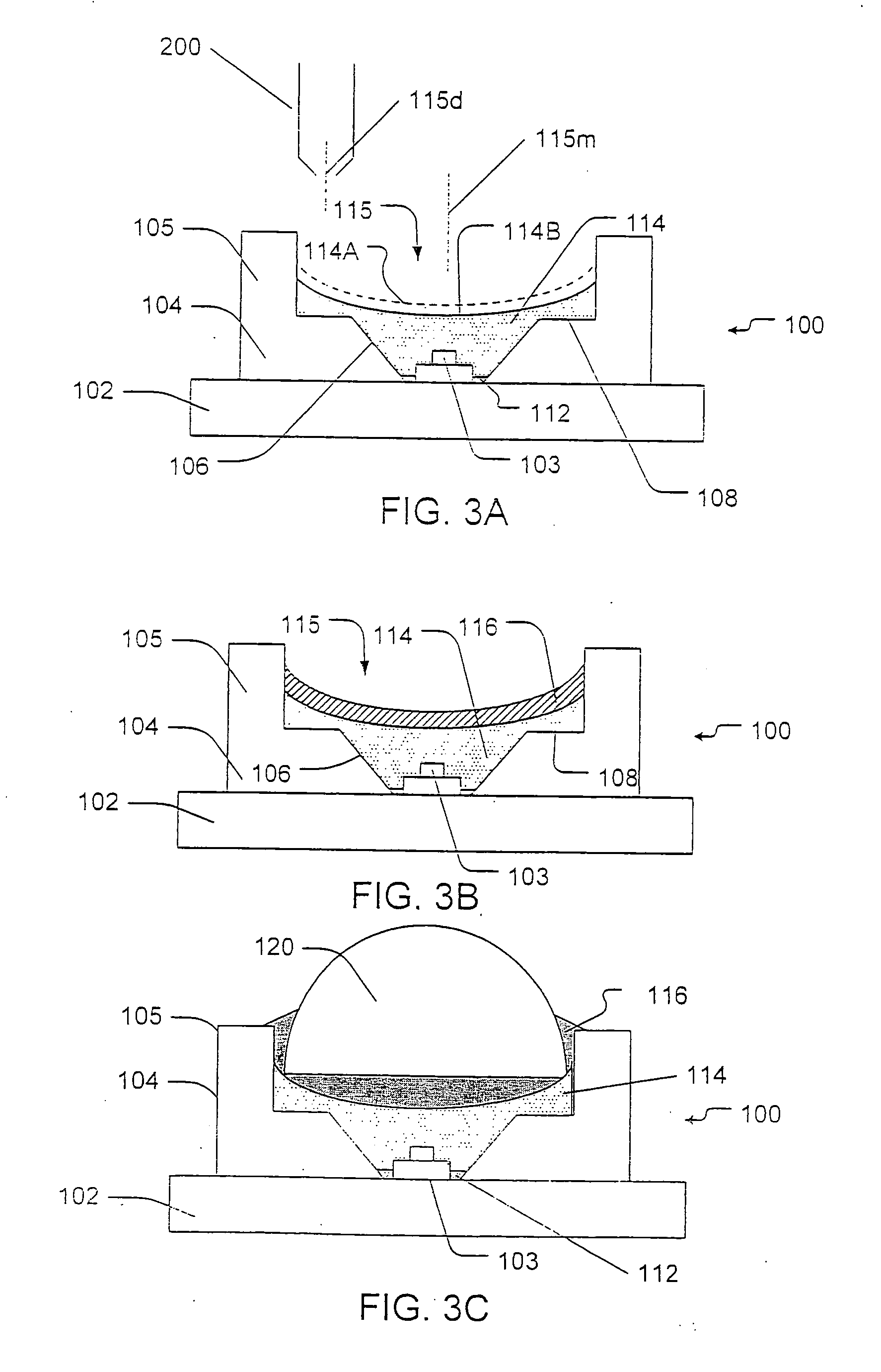
[0021] In yet further embodiments of the present invention, packaged semiconductor light emitting devices include a body having a sidewall portion defining a cavity and a light emitting device positioned in the cavity. A first quantity of cured encapsulant material is in the cavity including the light emitting device and a luminescent conversion element is on an upper surface of the first quantity of encapsulant material. The luminescent conversion element includes a wavelength conversion material. The packaged semiconductor light emitting device exhibits a variation of correlated color temperature (CCT)) across a 180 (+ / −90 from central axis)-degree range of emission angles of less than 2000K.

Problems solved by technology

Various problems may be encountered during packaging of a power LED for use as a light source.
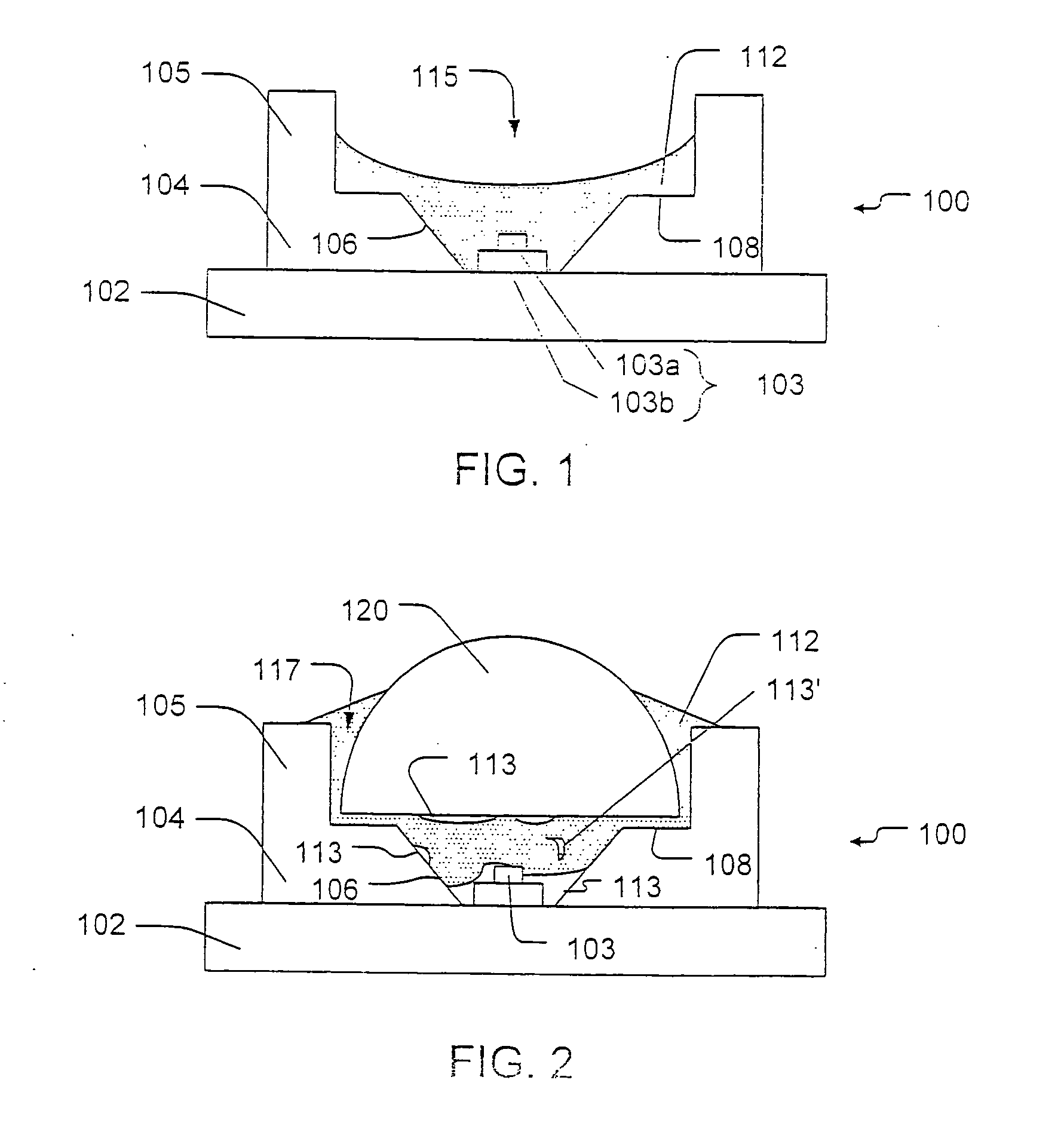
This movement, which may be referred to as squeeze-out, is generally undesirable for a number of reasons.
This may cause the lens to not float during thermal cycling and fail via delamination of encapsulation to other surfaces or via cohesive failure within the delamination, both of which may affect the light output.
The encapsulant material or gel is generally sticky and may interfere with automated processing tools used to manufacture the parts.
Moreover, the gel may interfere with light output from the lens 120, for example, by changing the light distribution pattern and / or by blocking portions of the lens 120.
The sticky gel may also attract dust, dirt and / or other contaminants that could block or reduce light output from the LED package 100.
However, encapsulant materials having a slight shrinkage factor with curing, such as a silicone gel, generally tend to contract during the heat curing process.
In addition, the coefficient of thermal expansion (CTE) effect generally causes higher floating of the lens at elevated temperatures.
The delamination may significantly affect optical performance, particularly when the delamination is from the die, where it may cause total internal reflection.
The contraction may also pull out air pockets from crevices (i.e, reflector) or from under devices (i.e., die / submount), which may then interfere with optical cavity performance.
However, the temperature of the package 100 may still increase significantly during operation.
This could cause delamination, voids, higher triaxial stresses and / or the like, which may result in less robust light emitting devices.

Method used


Image

  • Semiconductor light emitting devices including a luminescent conversion element and methods for packaging the same
  • Semiconductor light emitting devices including a luminescent conversion element and methods for packaging the same
  • Semiconductor light emitting devices including a luminescent conversion element and methods for packaging the same

Examples


Embodiment Construction

[0046] The present invention now will be described more fully hereinafter with reference to the accompanying drawings, in which embodiments of the invention are shown. This invention may, however, be embodied in many different forms and should not be construed as limited to the embodiments set forth herein. Rather, these embodiments are provided so that this disclosure will be thorough and complete, and will fully convey the scope of the invention to those skilled in the art. In the drawings, the size and relative sizes of layers and regions may be exaggerated for clarity. Like numbers refer to like elements throughout.

[0047] It will be understood that when an element such as a layer, region or substrate is referred to as being “on” another element, it can be directly on the other element or intervening elements may also be present. It will be understood that if part of an element, such as a surface, is referred to as “inner,” it is farther from the outside of the device than other...


PUM


Abstract

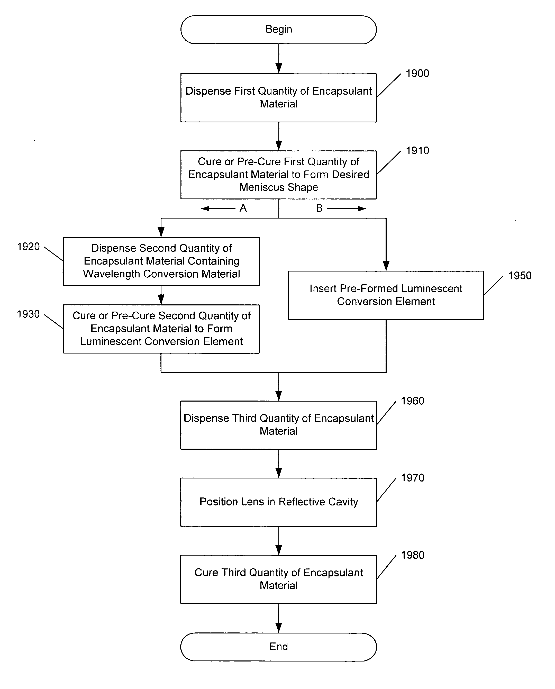
Methods of packaging a semiconductor light emitting device include dispensing a first quantity of encapsulant material into a cavity including the light emitting device. The first quantity of encapsulant material in the cavity is treated to form a hardened upper surface thereof having a selected shape. A luminescent conversion element is provided on the upper surface of the treated first quantity of encapsulant material. The luminescent conversion element includes a wavelength conversion material and has a thickness at a middle region of the cavity greater than proximate a sidewall of the cavity.

Description

RELATED APPLICATION [0001] This application claims the benefit of and priority to U. S. Provisional Patent Application No. 60 / 558,314, entitled “Reflector Packages and Methods for Forming Packaging of a Semiconductor Light Emitting Device,” filed Mar. 31, 2004, and U.S. Provisional Patent Application No. 60 / 637,700, entitled “Semiconductor Light Emitting Devices Including a Luminescent Conversion Element and Methods for Packaging the Same,” filed Dec. 21, 2004, the disclosures of which are hereby incorporated herein by reference as if set forth in their entirety.BACKGROUND OF THE INVENTION [0002] This invention relates to semiconductor light emitting devices and fabricating methods therefore, and more particularly to packaging and packaging methods for semiconductor light emitting devices. [0003] It is known to provide semiconductor light emitting device type light sources in packages that may provide protection, color selection, focusing and the like for light emitted by the light ...

Claims


Application Information

Patent Timeline
Patent Type & Authority Applications(United States)
IPC IPC(8): H01L21/00H01L33/50H01L33/52H01L33/58
CPCH01L33/507H01L33/52H01L33/58H01L2933/0041H01L2924/181H01L2924/00012
Inventor LEUNG, MICHAELCOLEMAN, THOMAS G.BECERRA, MARYANNE
Owner CREELED INC
Learn More