Pressure sensor

a technology of pressure sensor and pressure sensor, which is applied in the direction of instruments, electrical appliances, basic electric elements, etc., can solve the problems of unsuitable for high-speed operations with relative low bandwidth, and achieve the effect of high sensitivity and higher bandwidth

Inactive Publication Date: 2005-10-06
ASML HLDG NV
View PDF26 Cites 10 Cited by
  • Summary
  • Abstract
  • Description
  • Claims
  • Application Information

AI Technical Summary

Benefits of technology

[0006] The present invention is directed to high sensitivity, low pres

Problems solved by technology

The relatively low bandwidths are not suitable for higher speed op

Method used


Image

  • Pressure sensor
  • Pressure sensor
  • Pressure sensor

Examples


Embodiment Construction

I. Introduction

[0024] The present invention is directed to low pressure air gauges having higher bandwidths than are presently available. The present invention can be used in, for example, and without limitation, lithography proximity sensing and lithography topographical mapping.

II. High Bandwidth, Low Differential Pressure Sensing

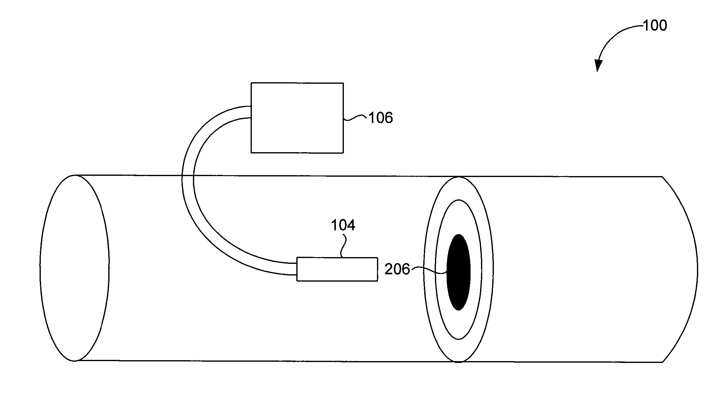
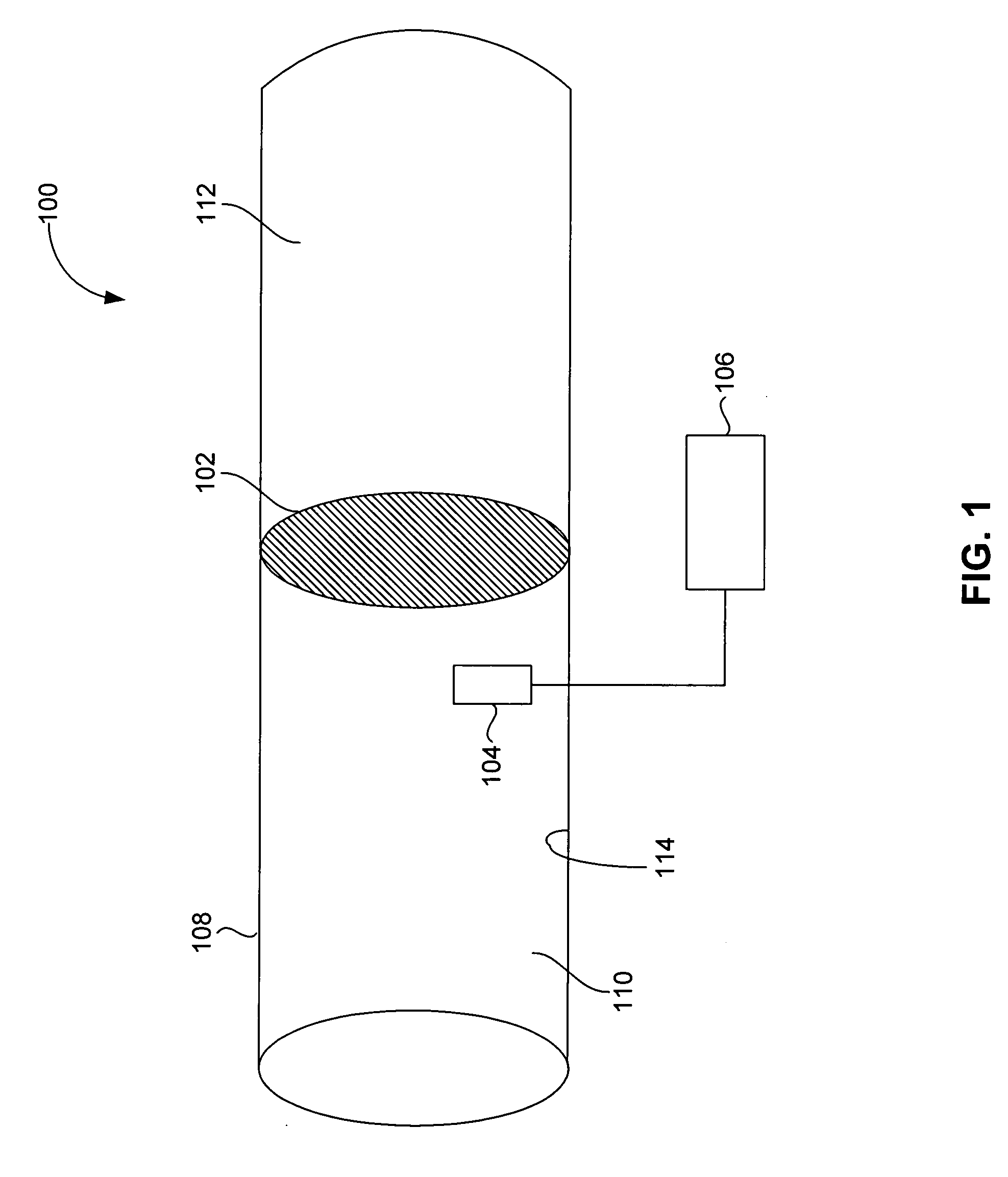
[0025]FIG. 1 is a side plan view of a pressure sensor 100 including a flexing plate or diaphragm 102, a diaphragm displacement sensor 104 (hereinafter “sensor”104) located proximate to the diaphragm 102, and a monitor and control system 106 electrically coupled (wired or wireless) to the sensor 104. The sensor 104 is proximate to the diaphragm, but not necessarily in physical contact with the diaphragm.

[0026] The diaphragm 102 and the sensor 104 are positioned within a body 108, between a first area 110 and a second area 112. The pressure sensor 100 determines a pressure difference between the first area 110 and the second area 112.

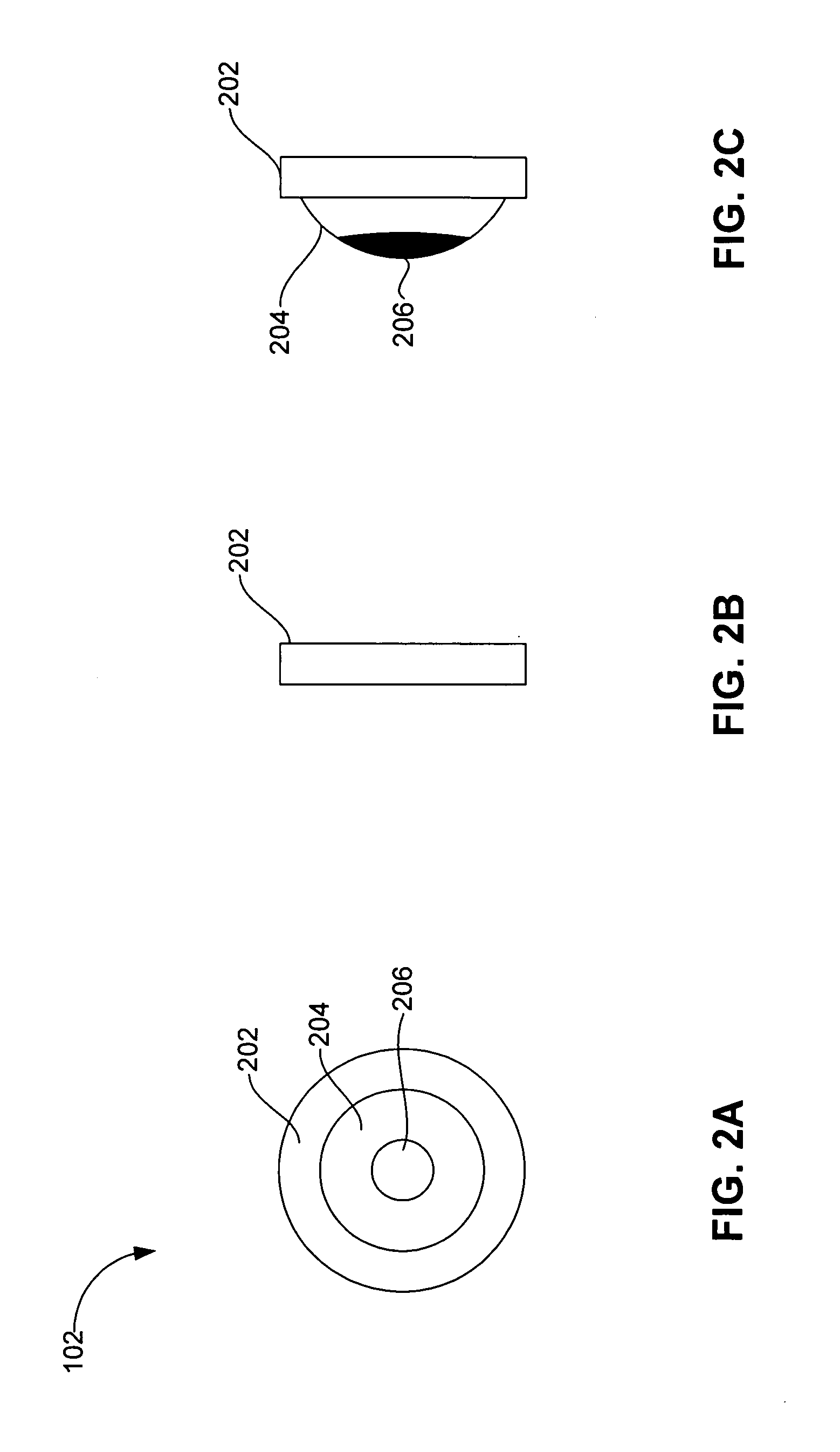
[0027]FIG. 2A is a...


PUM


Abstract

A pressure gauge includes a diaphragm having a substantially rigid outer portion and a displaceable inner portion that displaces in response to a pressure difference between first and second sides of the diaphragm. The pressure gauge further includes a sensor located proximate to the diaphragm and adapted to sense the displacement of the diaphragm inner portion. The pressure gauge further includes a monitor and control system coupled to the sensor (wired or wireless), and adapted to determine the pressure difference from the displacement of the diaphragm. The sensor and the monitor and control system can be implemented with one or more optical sensing designs, capacitive sensing designs, or other devices used to measure sub-micron displacements. For low pressure applications, such as lithography applications, the diaphragm is sensitive to pressure changes in a range of approximately 0.1 to 0.5 inches of water. The diaphragm and sensor have a relatively high bandwidth and can thus be implemented in relatively high speed applications. The invention can be implemented in, for example, lithography proximity sensing equipment and lithography topographical mapping equipment.

Description

BACKGROUND OF THE INVENTION [0001] 1. Field of the Invention [0002] The invention relates to high sensitivity, high bandwidth, low pressure sensors and, more particularly, to the application of these devices in air gauges for use in, for example, lithography devices. [0003] 2. Related Art [0004] Conventional low pressure air gauges utilize mass flow sensors, which have relatively long response times, or low bandwidths, typically in the range of a tens of Hz. The relatively low bandwidths are not suitable for higher speed operations, such as, for example, lithography scanning applications. [0005] What are needed therefore are high sensitivity, low pressure air gauges having higher bandwidths than are presently available. SUMMARY OF THE INVENTION [0006] The present invention is directed to high sensitivity, low pressure air gauges having higher bandwidths than are presently available. [0007] A pressure sensor in accordance with the invention includes a diaphragm having a substantially...

Claims


Application Information

Patent Timeline
IPC IPC(8): G01L9/00H01H35/34
CPCG01L9/0077G01L9/0072G01L11/02
Inventor GAJDECZKO, BOGUSLAWVIOLETTE, KEVIN J.
Owner ASML HLDG NV
Why Eureka
Try Eureka