
Aircraft engine sensor network using wireless sensor communication modules

a sensor network and aircraft engine technology, applied in the field of sensor networks, can solve the problems of increasing the complexity of the system, and increasing the weight and cost of the overall system

Active Publication Date: 2005-09-29
HONEYWELL INT INC
View PDF23 Cites 65 Cited by
  • Summary
  • Abstract
  • Description
  • Claims
  • Application Information

AI Technical Summary

Benefits of technology

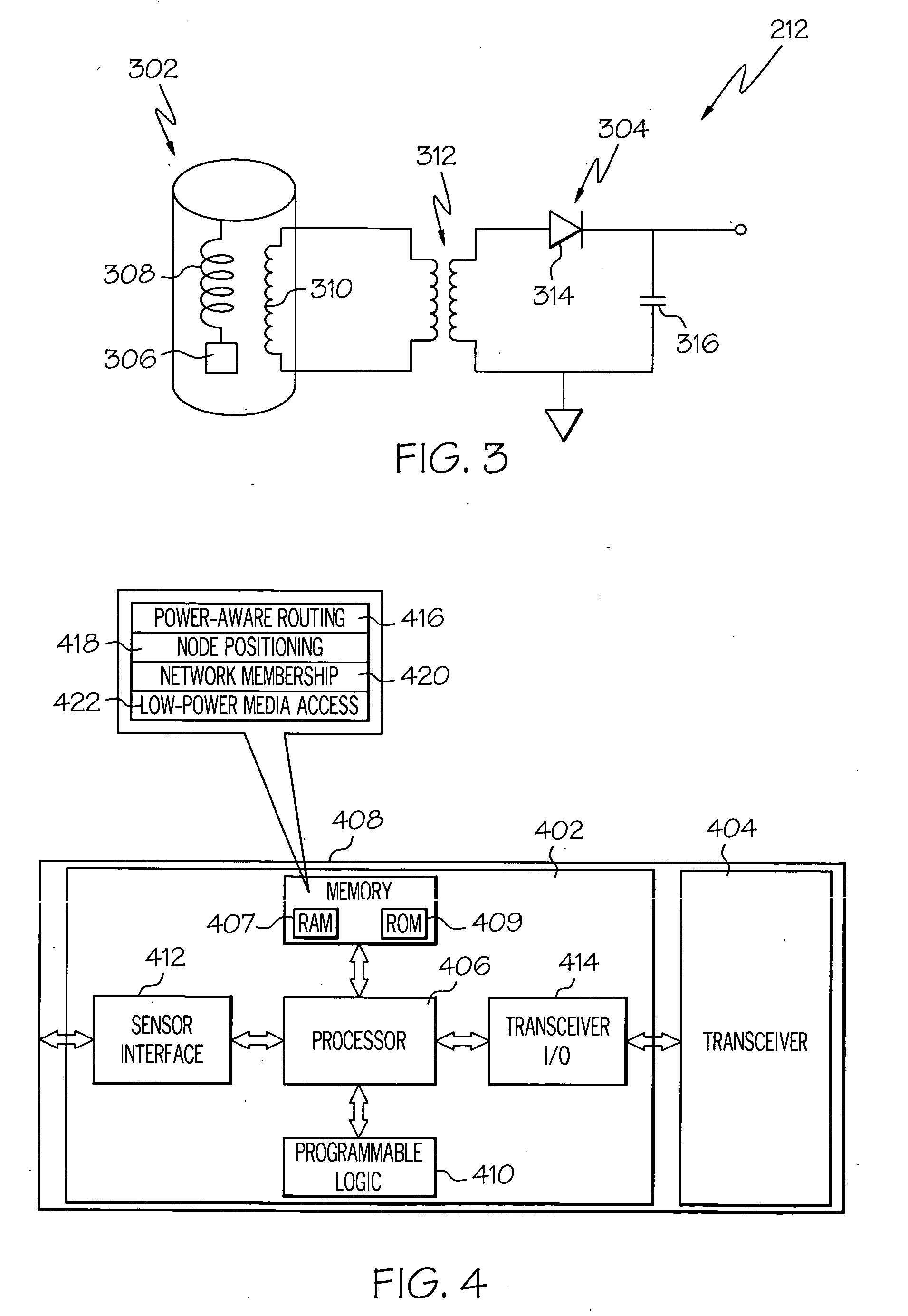
[0006] In another exemplary embodiment, an ad-hoc sensor communication network includes a plurality of wireless sensor communication modules. Each communication module is in operable communication with one or more other wireless sensor communication modules in the sensor communication network, and each communication module includes a sensor, a controller, and a transceiver. The sensor is operable to sense a physical parameter and supply sensor data representative thereof. The controller is configured to receive power capability data representative of power capability of other sensor communication modules in the sensor network and is operable, in response thereto, to determine a data transmission route through the sensor network based at least in part on the power capability data, and to supply transmission route data representative thereof. The transceiver is configured to receive the sensor data and is operable to modulate the sensor data with a radio frequency (RF) signal to thereby generate RF modulated sensor data. The transceiver is additionally coupled to receive the transmission route data and is operable, in response thereto, to transmit the RF modulated sensor data to a sensor network node in the determined transmission route.
[0007] In yet another exemplary embodiment, an ad-hoc aircraft engine sensor

Problems solved by technology

Modern physical systems, such as those used in aircraft, are becoming more and more complex.
This increase in system complexity has led to an increased desire for automated prognostic and health monitoring systems.
These wiring and wiring harnesses used to couple the sensors to the central processing unit can increase overall system weight and cost, and can reduce overall system reliability.

Method used


Image

  • Aircraft engine sensor network using wireless sensor communication modules
  • Aircraft engine sensor network using wireless sensor communication modules
  • Aircraft engine sensor network using wireless sensor communication modules

Examples


Embodiment Construction

[0016] The following detailed description is merely exemplary in nature and is not intended to limit the invention or the application and uses of the invention. Furthermore, there is no intention to be bound by any theory presented in the preceding background of the invention or the following detailed description of the invention. In this regard, although the present embodiment is, for ease of explanation, depicted and described as being implemented in a multi-spool turbofan gas turbine jet engine system, it will be appreciated that it can be implemented in various other end-use systems and environments.

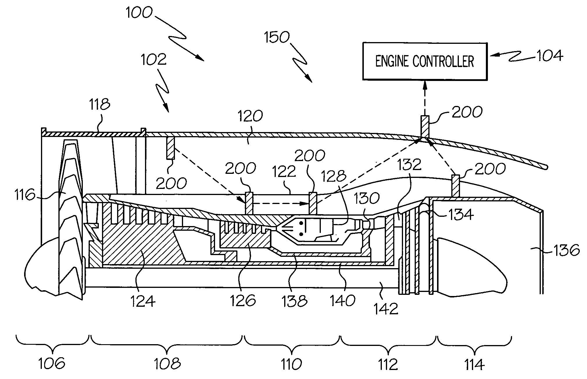
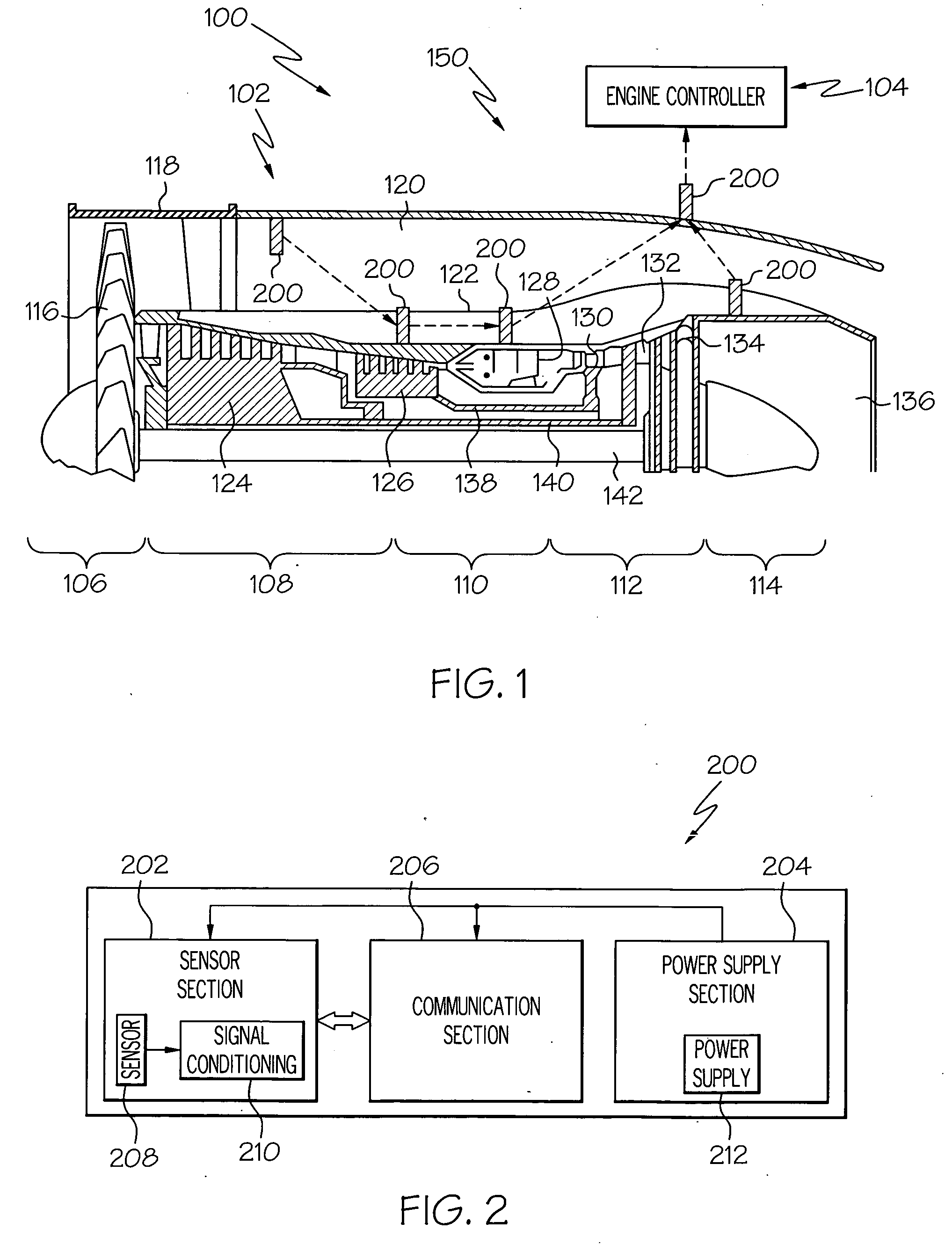
[0017] Turning now to the description and with reference first to FIG. 1, a simplified cross section view of an exemplary aircraft engine sensor communication system 100 is shown, and includes an aircraft engine 102 and an engine controller 104. In the depicted embodiment, the aircraft engine 102 is a multi-spool turbofan gas turbine engine. It will be appreciated, however, that thi...


PUM


Abstract

A wireless communication module is used to implement an ad-hoc wireless sensor network. The wireless communication module is configured to interface with numerous and varied types of sensors and, in one particular embodiment, is used to implement an ad-hoc wireless sensor network for an aircraft engine. The modules are also configured to implement various functions to optimize ad-hoc network functionality and to minimize the electrical power dissipated by each module in the ad-hoc network.

Description

FIELD OF THE INVENTION [0001] The present invention relates to sensor networks and, more particularly, to a wireless communication module that may be used to implement an ad-hoc wireless sensor network, and that provides a standard interface with numerous types of sensors. BACKGROUND OF THE INVENTION [0002] Modern physical systems, such as those used in aircraft, are becoming more and more complex. This increase in system complexity has led to an increased desire for automated prognostic and health monitoring systems. Many prognostic and health monitoring systems receive signals or data representative of one or more physical parameters from various components and / or subsystems within a system. The prognostic and health monitoring systems may then use the signals or data to, for example, predict future system performance and / or detect or predict potential component or subsystem faults. [0003] One particular aircraft system in which prognosis and health monitoring capability is becomi...

Claims


Application Information

Patent Timeline
IPC IPC(8): G01D5/48H04L12/56
CPCG01D21/00H04B7/18506Y02B60/50H04W40/10H04W84/18H04L45/00
Inventor BENSON, DWAYNE M.BAI, HAOWEI
Owner HONEYWELL INT INC
Learn More