
Faceplate groove pattern for a golf club putter head

a golf club and putter head technology, applied in the field of golf club putter head faceplate groove pattern, can solve the problems of reducing overall putting accuracy, and achieve the effects of improving overall directional accuracy, promoting early smooth ball roll, and minimizing initial ball skidding

Inactive Publication Date: 2005-09-22
BGI ACQUISITION
View PDF14 Cites 123 Cited by
  • Summary
  • Abstract
  • Description
  • Claims
  • Application Information

AI Technical Summary

Benefits of technology

[0006] In accordance with the invention, an improved golf club putter head is provided with a faceplate groove pattern configured to create an elevated center of gravity located above a vertical mid-point of a club head body or faceplate formed thereon. When the improved putter head of the present invention is used to strike a golf ball in the course of executing a putting stroke, the elevated center of gravity functions to minimize initial ball skidding and to promote early smooth ball roll toward a target such as a cup on a golf green. As a result, overall directional accuracy is improved.

Problems solved by technology

Unfortunately, ball skidding is associated with minimal ball movement control, and thereby detracts from overall putting accuracy.

Method used


Image

  • Faceplate groove pattern for a golf club putter head
  • Faceplate groove pattern for a golf club putter head
  • Faceplate groove pattern for a golf club putter head

Examples


Embodiment Construction

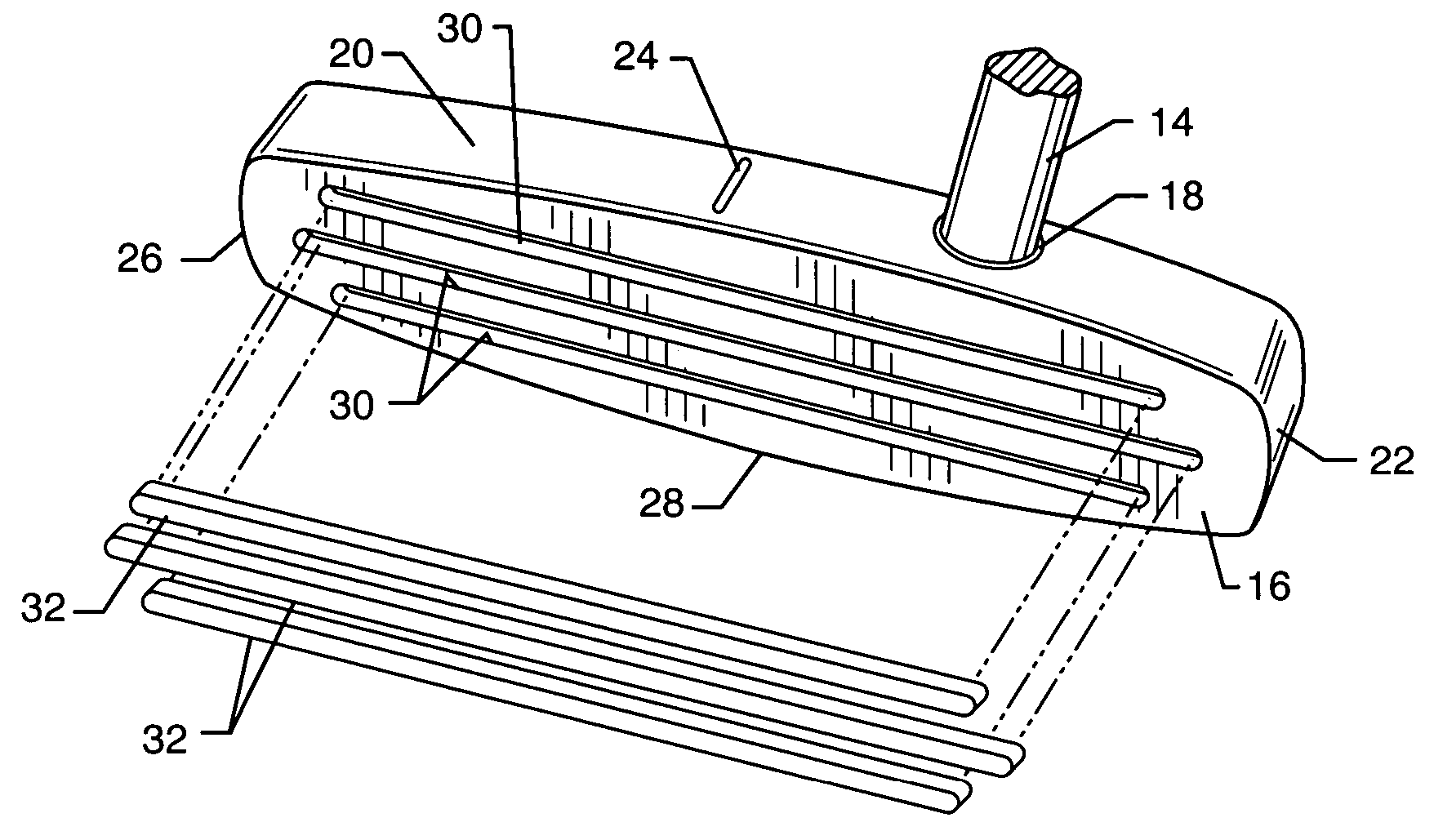
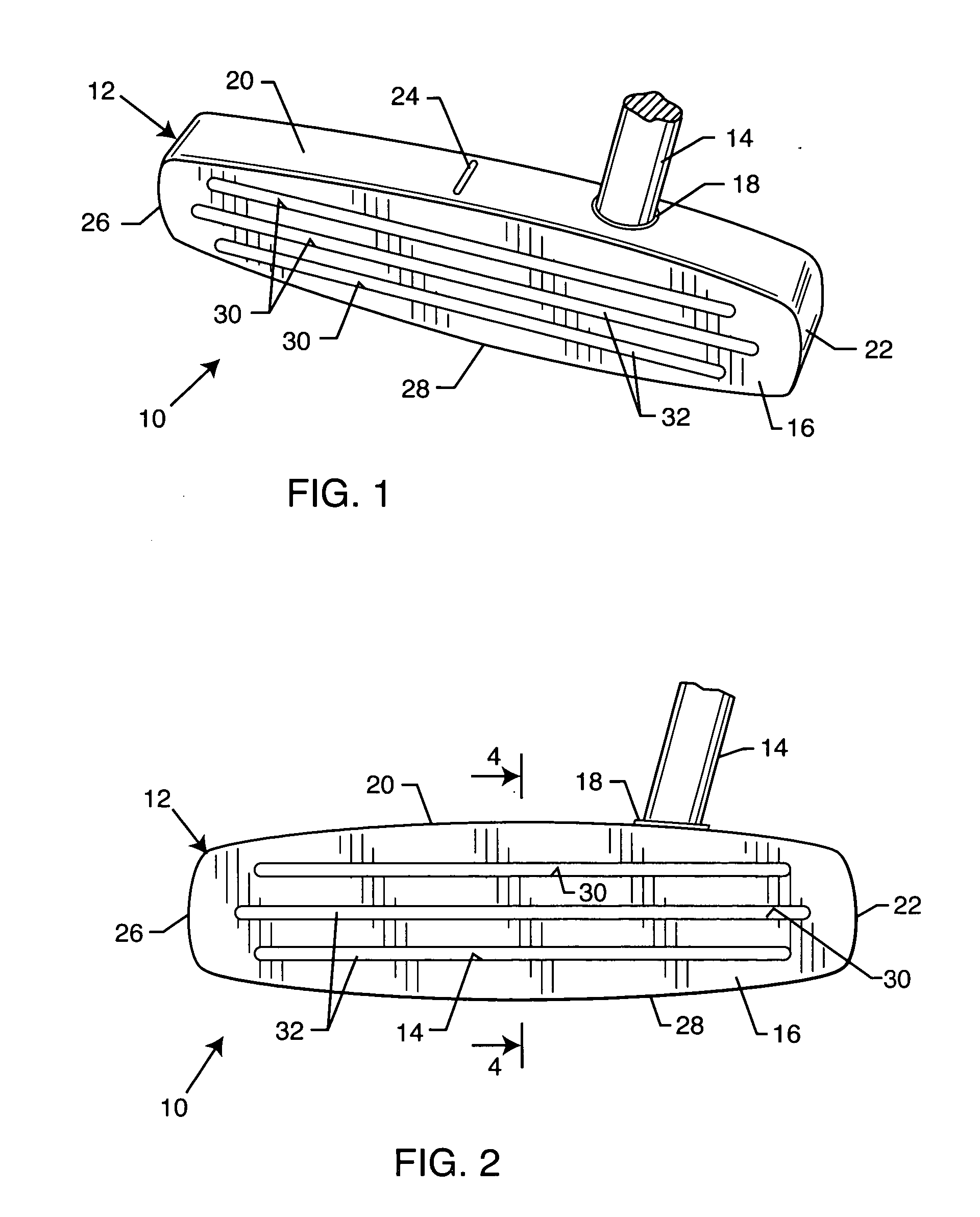
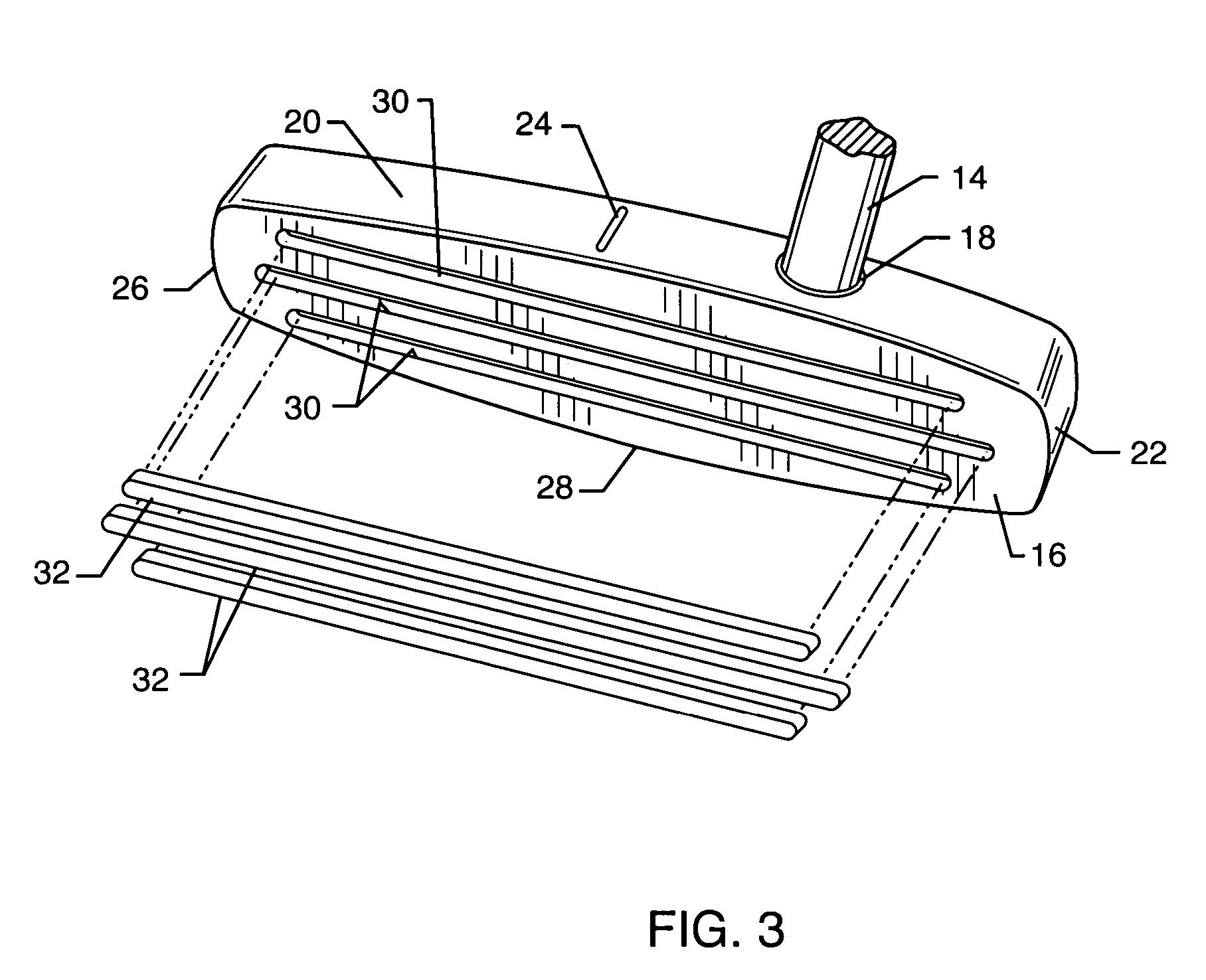
[0032] As shown in the exemplary drawings, an improved golf club putter head referred to generally in FIGS. 1-4 by the reference numeral 10 includes a club head body 12 adapted for mounting onto a lower end of a golf club shaft 14. This club head body 12 defines a forwardly presented faceplate 16 for striking impact with a golf ball 11 (FIG. 4) in the course of executing a putting stroke during a round of golf or the like. In accordance with the invention, the club head body 12 is weighted so that a center of gravity thereof is vertically elevated to a position disposed at least slightly and preferably a short distance above a vertical mid-point of the faceplate 16 and / or the club head body 12. With this configuration, upon impact with a golf ball, initial and relatively uncontrolled or minimally controlled skidding of the ball is significantly reduced. Instead, early and comparatively smooth ball rolling is promoted to achieve improved directional control and improved putting accur...


PUM


Abstract

A golf club putter head includes a faceplate groove pattern configured to provide the putter head with an elevated center of gravity. In one preferred form, a club head body defines a faceplate having at least one and preferably multiple elongated grooves formed therein to extend generally in a heel-to-toe direction, with at least one groove positioned above a vertical mid-point of the club head body. The groove depths progressively increase in a top-to-bottom direction so that the putter head center of gravity is elevated to a position spaced above the vertical mid-point of the club head body. When striking a golf ball, the elevated center of gravity functions to minimize initial ball skidding and to promote early smooth ball roll toward a target such as a cup on a golf green.

Description

BACKGROUND OF THE INVENTION [0001] This application claims the benefit of U.S. Provisional Applications 60 / 539,489, filed Jan. 26, 2004, and 60 / 553,866, filed Mar. 16, 2004. [0002] This invention relates generally to improvements in golf club heads of the type used for putting strokes. More particularly, this invention relates to an improved golf club putter head having a faceplate groove pattern designed for minimizing initial post-impact ball skidding, and to promote early smooth post-impact rolling of a golf ball toward a target such as a cup on a golf green or the like. [0003] Golf club putter heads are available in an extremely broad range of geometric shapes and sizes, with virtually every putter head design intended or otherwise promoted as encouraging or facilitating controlled and balanced impact with a golf ball to achieve improved directional accuracy and a corresponding stroke count reduction in a round of golf. In general, putter heads comprise a club head body mounted ...

Claims


Application Information

Patent Timeline
Patent Type & Authority Applications(United States)
IPC IPC(8): A63B53/04
CPCA63B53/0487A63B2053/0458A63B2053/0445A63B2053/0416A63B53/0416A63B53/0445A63B53/0458
Inventor BURROWS, BRUCE D.
Owner BGI ACQUISITION
Learn More