Eureka AIR delivers breakthrough ideas for toughest innovation challenges, trusted by R&D personnel around the world.

Welding machine and welding method

a welding method and welding machine technology, applied in the direction of machines/engines, mechanical equipment, manufacturing tools, etc., can solve the problems of degrading sealing performance and welding failure, and achieve the effect of reducing the fuel leakage of the injector

Inactive Publication Date: 2005-09-22
DENSO CORP
View PDF16 Cites 3 Cited by
  • Summary
  • Abstract
  • Description
  • Claims
  • Application Information

AI Technical Summary

Benefits of technology

[0012] It is a first object of an embodiment of the present invention to provide a welding machine and a welding method, for welding cylinder members together in the circular direction, which prevents the cylinder members from being deformed and which corrects the deformation of a portion to be welded. It is another object of an embodiment of the present invention to provide a welding method which prevents pores from being generated at a welded portion. It is another object of an embodiment of the present invention to provide a welding machine for reducing fuel leakage of an injector.

Problems solved by technology

However, when both cylinder members are welded to each other by applying energy to both at only one position, a problem occurs.
In a member requiring metal sealing, when the member is deformed by welding, sealing performance is degraded.
When pores are generated at the welded portion, welding failure may occur.

Method used


Image

  • Welding machine and welding method
  • Welding machine and welding method
  • Welding machine and welding method

Examples


Embodiment Construction

[0039] The following description of the preferred embodiments is merely exemplary in nature and is in no way intended to limit the invention, its application, or uses.

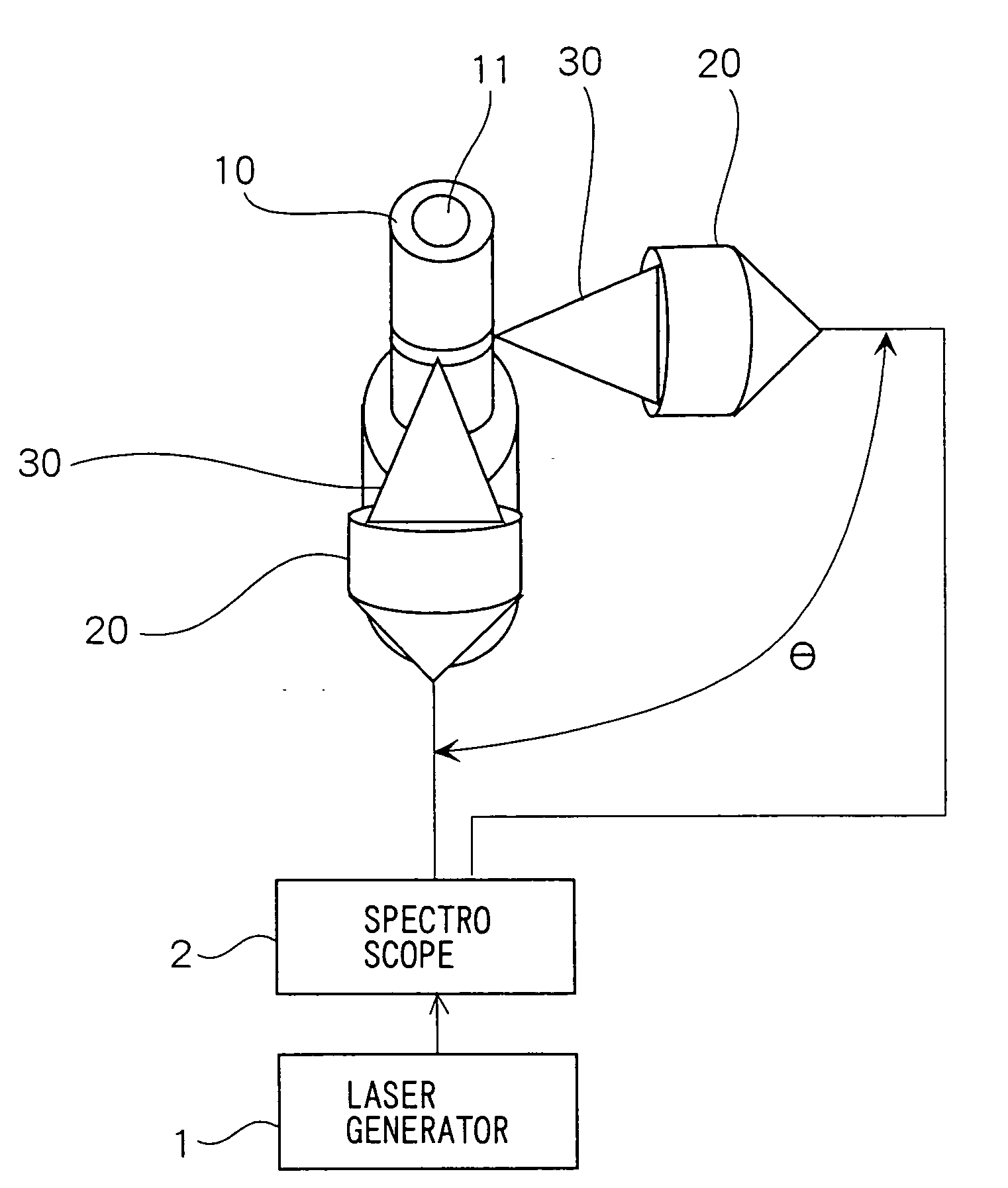
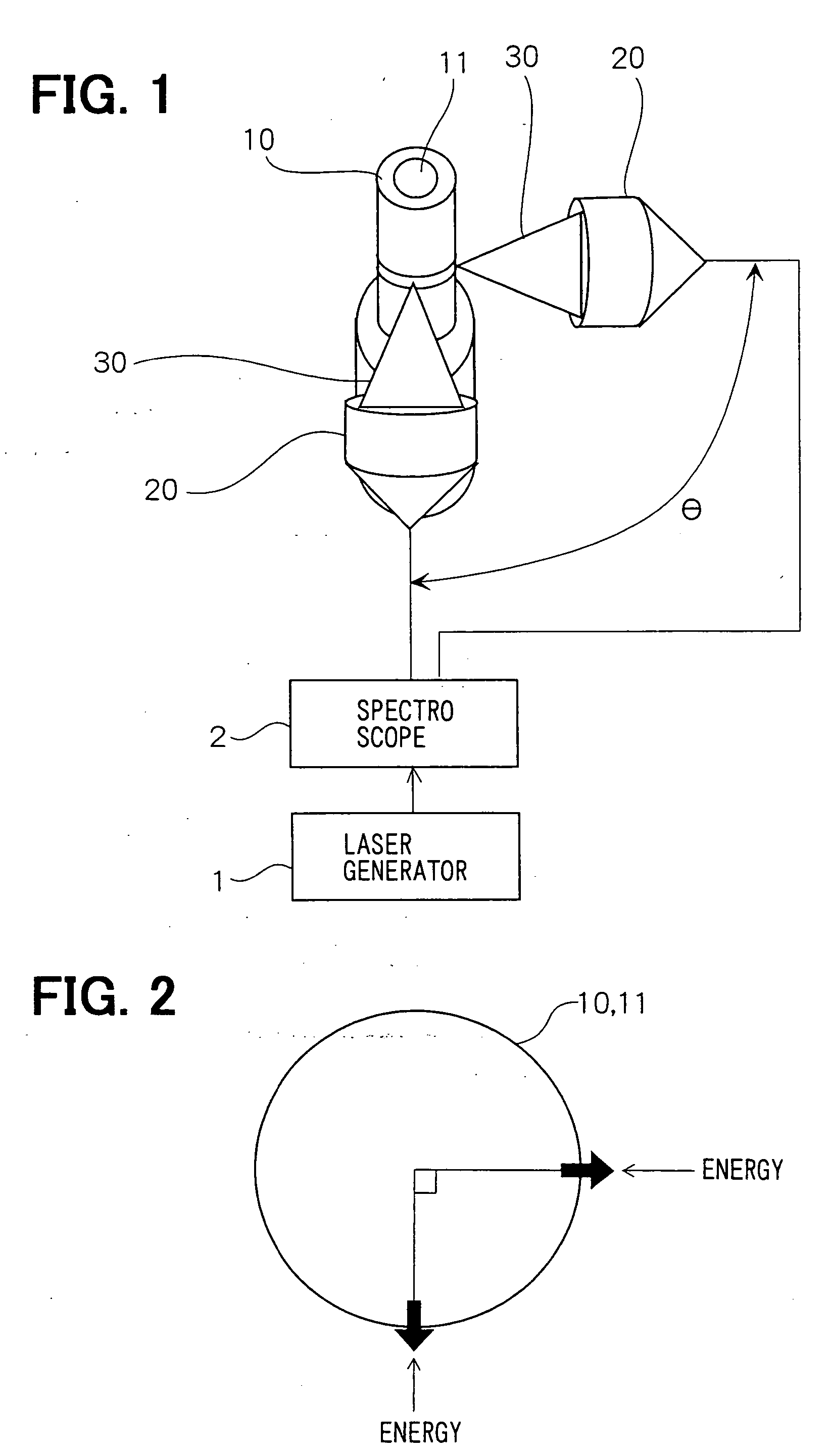
[0040]FIG. 1 is a schematic view showing a welding machine in an embodiment of the present invention. An outer cylinder member 10 and an inner cylinder member 11 have circular cross-sections, and the inner cylinder member 11 is press-fitted into the outer cylinder member 10. For example, the outer and inner cylinder members 10, 11 could be a combination of a housing of an injector and a nozzle body, respectively.

[0041] A laser generator 1 as an energy source generates a high-energy laser beam such as an yttrium aluminum garnet (YAG) laser beam and a carbon oxide (CO2) laser beam. A laser beam, generated by the laser generator 1, is dispersed in two directions by a spectroscope 2. Two dispersed laser beams are focused on the outer cylinder member 10 by two optical heads 20 as energy-applying units, respectively. The o...


PUM

PropertyMeasurementUnit
angleaaaaaaaaaa
angleaaaaaaaaaa
angleaaaaaaaaaa

Abstract

In a welding machine and welding method, for welding cylinder members together about an outside diameter, which prevents the cylinder members from being deformed and corrects the deformation of a portion to be welded, a laser beam, generated by a laser generator, is dispersed in two directions by a spectroscope. The laser beams focus on an outer cylinder member using two optical heads, respectively, in a plane perpendicular to a center axis of outer cylinder member. The optical heads are separated from each other by approximately 90 degrees in the plane. The outer and inner cylinder members are welded to each other in the circular direction using laser beams. Therefore, directions, in which the cylinder members are deformed due to the laser beams, are perpendicular to each other creating uniform radial deformation.

Description

CROSS-REFERENCE TO RELATED APPLICATION [0001] This application is based on and incorporates herein by reference Japanese Patent Application No. 2001-50015 filed on Feb. 26, 2001, and Japanese Patent Application No. 2002-11556 filed on Jan. 21, 2002. BACKGROUND OF THE INVENTION [0002] 1. Field of the Invention [0003] The present invention relates to a welding machine and a welding method, by which and in which cylinder members are connected together. Specifically, one cylinder member is inserted within another cylinder member and energy is applied to the outside cylinder member, around an outside diameter of the cylinder member, using an energy-applying unit(s), so that the cylinder members become welded together. [0004] 2. Description of Related Art [0005] Generally, when multiple cylinder members are welded together around their peripheries, energy is applied to the cylinder members in a single direction using an energy source. An example is shown in FIG. 8. First, an inner cylinde...

Claims


Application Information

Patent Timeline
Patent Type & Authority Applications(United States)
IPC IPC(8): B23K26/00F02M51/06B23K26/064B23K26/067B23K26/21B23K26/28
CPCB23K26/0621B23K26/285B23K26/067B23K26/0619B23K26/282
Inventor SHIRAI, HIDEAKIMURAKAMI, KOJITANAKA, NORIOKARIYA, YOSHIKINISHINA, HIROYUKIHOKAO, TAKAYUKI
Owner DENSO CORP
Why Eureka
Eureka Blog
Learn More