
Flexible deployment of software applications

Active Publication Date: 2005-09-15
RAMCO SYSTEMS
View PDF17 Cites 47 Cited by
  • Summary
  • Abstract
  • Description
  • Claims
  • Application Information

AI Technical Summary

Problems solved by technology

Because of this, for multi-layered applications, topology selection becomes a most problematic task for application deployment.
A related issue, hardware sizing, is sometimes arrived at after making an estimate about the size of the applications and the appropriate topology selection.
While fine-tuning the live applications for factors such as those mentioned above, a trial and error approach to arrive at a final optimal solution is unavoidable.
The use of manual systems to deploy such complex applications with a lot of interdependencies is fraught with dangers (such as missed elements), and do not explicitly formalize software deployment and roll out.
Moreover, when there is a reorganization and consequent redeployment, existing practices are cumbersome and are dependent on detailed manual documentation of deployment maps.
The current set of technologies and distributed processing schemes make the task even tougher.

Method used


Image

  • Flexible deployment of software applications
  • Flexible deployment of software applications
  • Flexible deployment of software applications

Examples


Embodiment Construction

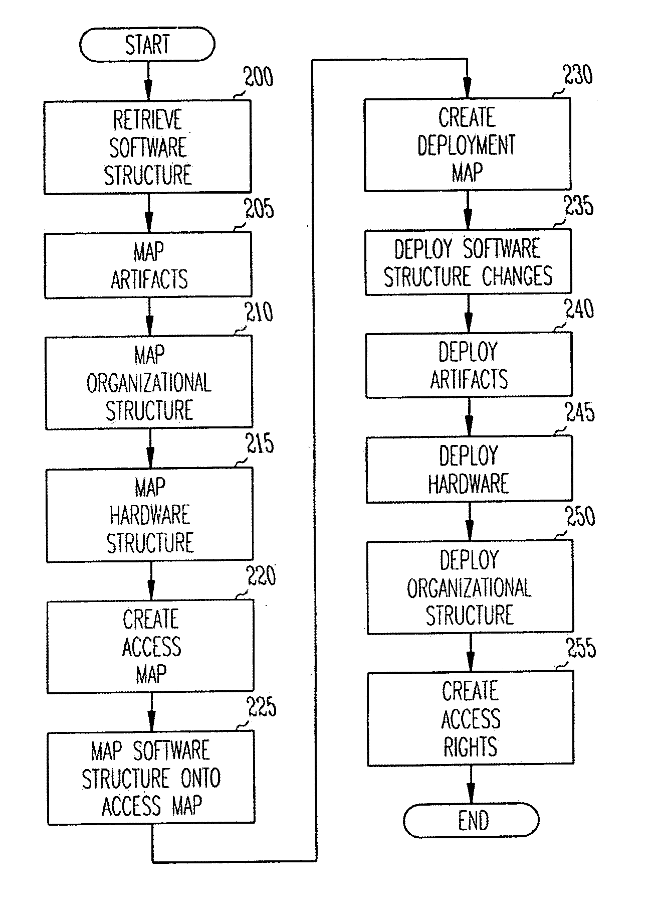
[0017] An embodiment of the invention uses a model-driven software development and deployment scheme to automate deployment of software. From information captured in the model, a deployment scheme can be developed according to the topology selection.

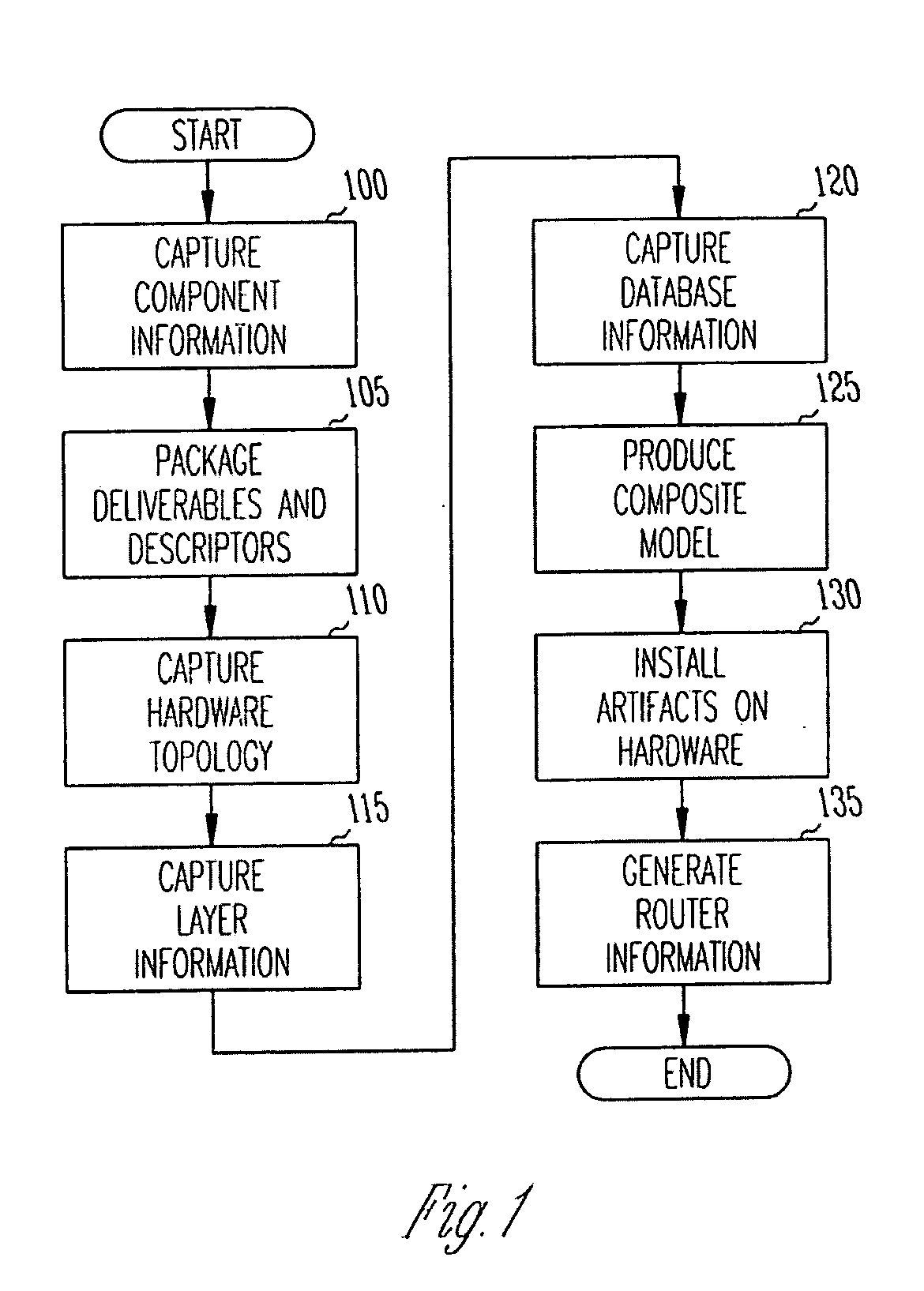
[0018]FIG. 1 illustrates an embodiment of the invention. In a model-driven approach for software development in block 100, all the information about components of a software application and their interactions are captured in the model in terms of the services offered by the components and used by the other components. From this information, in block 105, the deliverables for a component can be automatically packaged along with the necessary deployment descriptors.

[0019] The topology of the hardware is also captured in the model at block 110. This includes the details of machines on which the software will run, and their configuration information like operating systems and IP-addresses. The topology of the software includes the type of ...


PUM


Abstract

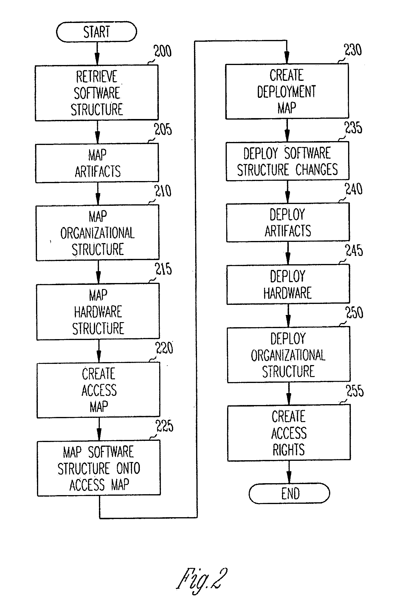
A system and method for deploying software is disclosed. In one embodiment, information regarding software components and their interactions, deliverables and deployment descriptors, hardware topology, layer information, and database information are all captured in a model. The model in then used to install the software on a particular machine. In another embodiment, an organizational structure is used to create an access map, and access rights to the installed software are generated and enforced.

Description

RELATED APPLICATIONS [0001] Benefit is claimed under 35 U.S.C. 119(e) to U.S. Provisional Application Ser. No. 60 / 553,635, entitled “An Approach for Automating Deployment of Software Applications Independent of Technology Platform” by inventor Parthasarathy Sundararajan et al., filed Mar. 16, 2004, which is herein incorporated in its entirety by reference for all purposes. [0002] Benefit is claimed under 35 U.S.C. 119(e) to U.S. Provisional Application Ser. No. 60 / 553,269, entitled “An Approach to Flexible Software Deployment of Business Component” by inventor Parthasarathy Sundararajan et al., filed Mar. 15, 2004, which is herein incorporated in its entirety by reference for all purposes. [0003] Benefit is claimed under 35 U.S.C. 119(e) to U.S. Provisional Application Ser. No. 60 / 553,254, entitled “Software Structure Driven Approach to Implementation” by inventor Parthasarathy Sundararajan et al., filed Mar. 15, 2004, which is herein incorporated in its entirety by reference for al...

Claims


Application Information

Patent Timeline
IPC IPC(8): G06F9/44G06F9/445
CPCG06F8/71
Inventor SUNDARARAJAN, PARTHASARATHYJAYARAMAN, SHYAMALASATHIAVAGEESWARAN, SURESHMEENAKSHISUNDARAM, KRISHNAMOORTHYDEVALLA, RAGHURAMPANDIMANI, SRIRANGANKRISHNAN, NATARAJAN
Owner RAMCO SYSTEMS
Learn More