
Data transfer device and method

a data transfer device and data technology, applied in the direction of digital signal error detection/correction, moving record carriers backward/forward, magnetic tape recording, etc., can solve problems such as errors when reading data from a medium

Inactive Publication Date: 2005-09-15
HEWLETT PACKARD DEV CO LP
View PDF10 Cites 3 Cited by
  • Summary
  • Abstract
  • Description
  • Claims
  • Application Information

AI Technical Summary

Benefits of technology

[0028] the displacement element being arranged to be moveable to said second condition in which, in use, relative displacement between at least a said transfer element and said transfer zones occurs such that a transfer zone that is aligned with one of said transfer elements when said displacement element is in said first condition is aligned with the other of said transfer elements, thereby enabling a said transfer zone to be alignable selectively with said first and said second data transfer elements at different times.
[0050] Should a read error of data stored on the medium occur this arrangement allows a read retry to be attempted using a different read head than that which registered the error thus overcoming, at least partially, at least one of the problems / difficulties mentioned hereinbefore.
[0052] The transfer elements may be write heads, read heads or a combination of both read and write heads. The transfer elements may be arranged in a read after write configuration. These alternatives allow the data to be either re-read or re-written using different heads thereby increasing the likelihood of an apparently errored section of data storage medium being successfully read.

Problems solved by technology

Errors can occur when reading data from a medium.
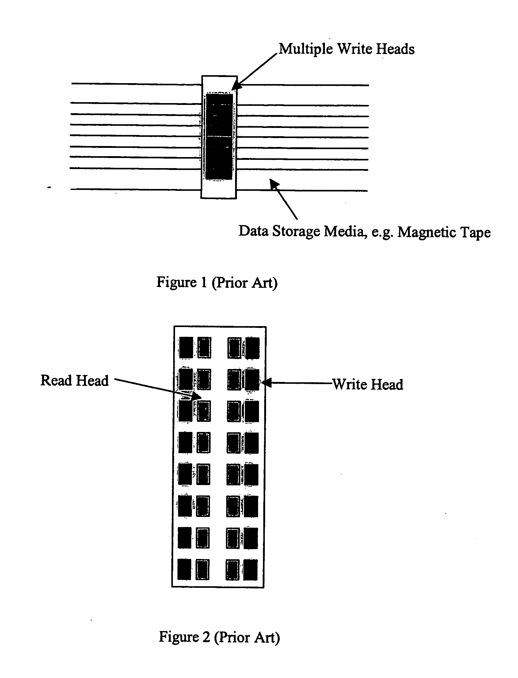
Typical contributing factors to the occurrence of read errors include: i) a read head being narrower than a data track and therefore not being able to read all of the data stored on the track; ii) a read head being wider than a data track and therefore picking up signals from a data track, or tracks, alongside that being read; iii) small particles of magnetic debris, from the surface of media or elsewhere, interposing in the small gap, typically a few μm, between the media and the head and interfering with the reading of the data.

Method used


Image

  • Data transfer device and method
  • Data transfer device and method
  • Data transfer device and method

Examples


first embodiment

[0104] The specific methods and advice according to the present invention described herein are concerned with magnetic tape recording devices having substantially static, aligned read / write heads in which elongate tape is drawn past the heads in a direction transverse to axis of alignment of the heads.

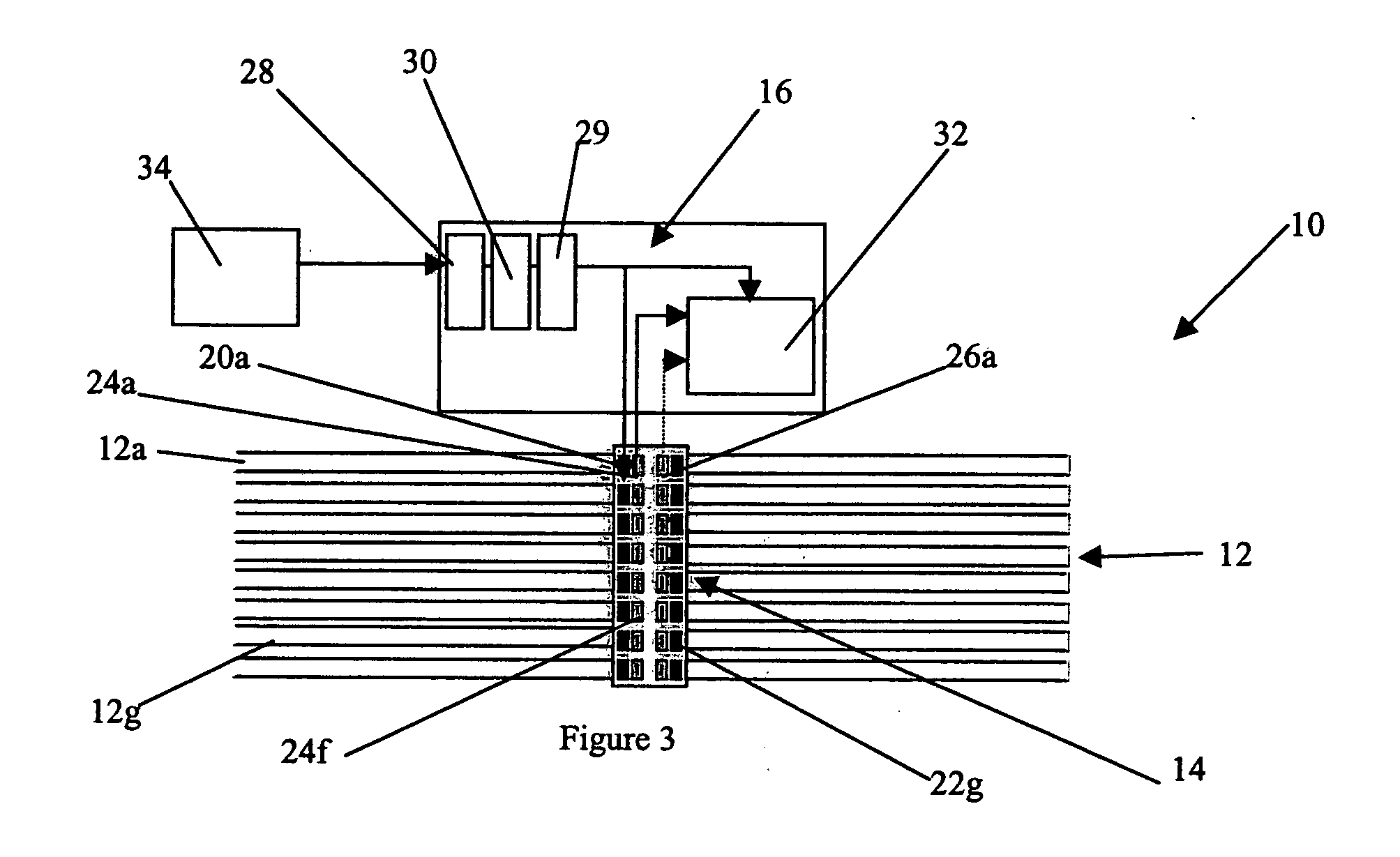
[0105] Referring now to FIG. 3, a magnetic tape reader 10 arranged to read a tape 12 includes a head block 14 and a control unit 16.

[0106] The tape 12 has a plurality of physical data tracks 12a-h that extend over its length. It will be appreciated that although eight tracks are shown there will be many more physical data tracks, typically up to 512 present on the tape 12. Each tape 12 will have a servo track that is written onto the blank tape during manufacture which actively controls the motion of the head block 14 over the tape. The servo track is typically bound and runs parallel to each set of eight tracks 12a-n.

[0107] The head block 14 has two parallel columns of eight write h...

second embodiment

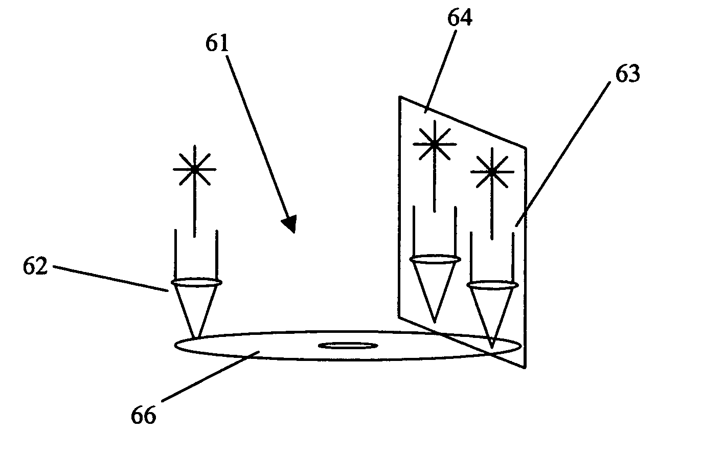
[0132] In the present invention described hereinbefore the re-reading of the portion of the tape initially read by the first head 24a by another head involves effecting a relative displacement between the head block 14 and tape 12 by the servo 18. This displacement aligns a second read head 26b that is spaced apart from the first head in a direction that is transverse to the direction of travel of the tape with the track 12a, the tape is rewound and the head 26b attempts to read the data (Step 58). The re-read data undergoes an error detection code check as described hereinbefore (Step 56). Numerous attempts to read the data can be made using numerous. read heads by repeatedly displacing the head block 14a.

[0133] If after a number of retries using the second head 26b,26a the data has still not been successfully read the tape drive 10 returns a read error signal to a user (Step 60).

[0134] In a further embodiment of the present invention, shown in FIG. 10, a CD re-writer 61 includes...


PUM


Abstract

A data transfer device adapted to transfer data from a data storage medium having at least one data storage element the data transfer device comprising a head block having first and second transfer elements. The first and second transfer elements arranged such that, when, in use, the data storage medium moves past the first and second transfer elements said at least one data storage element is aligned with both of said first and second data transfer elements. The first data transfer element is arranged to read data from a portion of said at least one data storage element at a different time to the second data transfer element being arranged to read data from said portion of said at least one data storage element.

Description

CROSS-REFERENCE TO RELATED APPLICATION [0001] This is a divisional and claims the benefit under 35 U.S.C. §120 of U.S. application Ser. No. 09 / 917,784, filed Jul. 31, 2001, the entire disclosure of which is hereby incorporated by reference.FIELD OF THE INVENTION [0002] This invention relates to a data transfer device, and method of data transfer. More particularly, but not exclusively, it relates to a device and method for reading from a data storage medium with increased reliability. BACKGROUND TO THE INVENTION [0003] Errors can occur when reading data from a medium. For example, if an error occurs when reading data from a tape it is usual to retry to read the data by rewinding the tape and running it past the read head again. This cycle can be repeated, for example, up to 56 times for a tape drive before the control unit reports an error to a user of the device. In hard disc drives there may be up to 100 retries prior to the reporting of an error to the user. [0004] Typical contri...

Claims


Application Information

Patent Timeline
IPC IPC(8): G11B5/00G11B5/008G11B5/012G11B5/49G11B7/0045G11B7/08G11B11/105G11B15/087G11B15/12G11B15/20G11B20/10G11B20/18
CPCG11B5/00813G11B5/012G11B5/4969G11B7/00458G11B7/08G11B11/10556G11B2005/001G11B15/087G11B15/125G11B15/20G11B20/10G11B20/18G11B11/10595
Inventor RUSHTON, NIGEL KEVINSIERRA, LAURA LOREDOBARTLETT, PAUL FREDERICK
Owner HEWLETT PACKARD DEV CO LP
Learn More