
Cylinder and device for guiding a material web

a technology of cylinder and material web, which is applied in the direction of printing presses, rotary presses, printing presses, etc., can solve the problems of bending the shell, affecting the exact guidance of the web, and affecting the accuracy of the web, so as to achieve the effect of free indexing errors and precise web guidan

Inactive Publication Date: 2005-09-15
OFFICINE MECCANICHE GIOVANNI CERUTTI
View PDF12 Cites 3 Cited by
  • Summary
  • Abstract
  • Description
  • Claims
  • Application Information

AI Technical Summary

Benefits of technology

[0019] The advantages to be obtained by the present invention consist, in particular, in that the device makes it possible, in an easy manner, to make the effective path of the web of material, for example the effective path of a paper web, variable over the width of the paper web from a fixed point, such as from a guide roller that is located upstream of the gap, to a fixed point that is located downstream of the gap. The inhomogeneity of the web tension which results from this variability of the path length, can be set in such a way that it exactly compensates for an inhomogeneity caused by the thickening of the forme cylinder. In this way, the stretching of the web can be made uniform over its entire width. A printing of the web, which is free of indexing errors, becomes possible over the entire width of the paper web.
[0029] Also advantageously, the cylinder has a rubber surface. The resilience of the cylinder rubber surface makes it easier to set an even pressure distribution along the clamping line.

Problems solved by technology

Such a deformation can be the source of indexing errors when printing on the web.
The chambers will expand or extend, after being charged with pressure, and will thus cause bending of the shell.
An exact guidance of a web, in a manner which is free of indexing errors, is made difficult, particularly in connection with rotogravure printing presses of great width, because it is extremely difficult to produce forme cylinders.
As a result of this uneven traction force, an uneven tension profile is generated within the paper web over its width.
Since, in the course of the paper webs being processed in such a press, the paper webs absorb moisture, their stretching ability increases, so that an uneven stretching of the web, in accordance with the uneven tension profile, can occur.
The result can be indexing errors.
However, in this case, it is disadvantageous that, on the other side of the paper web, the indexing errors become even greater, and that there is a danger of a lateral drift-off of the paper web.

Method used


Image

  • Cylinder and device for guiding a material web
  • Cylinder and device for guiding a material web
  • Cylinder and device for guiding a material web

Examples


Embodiment Construction

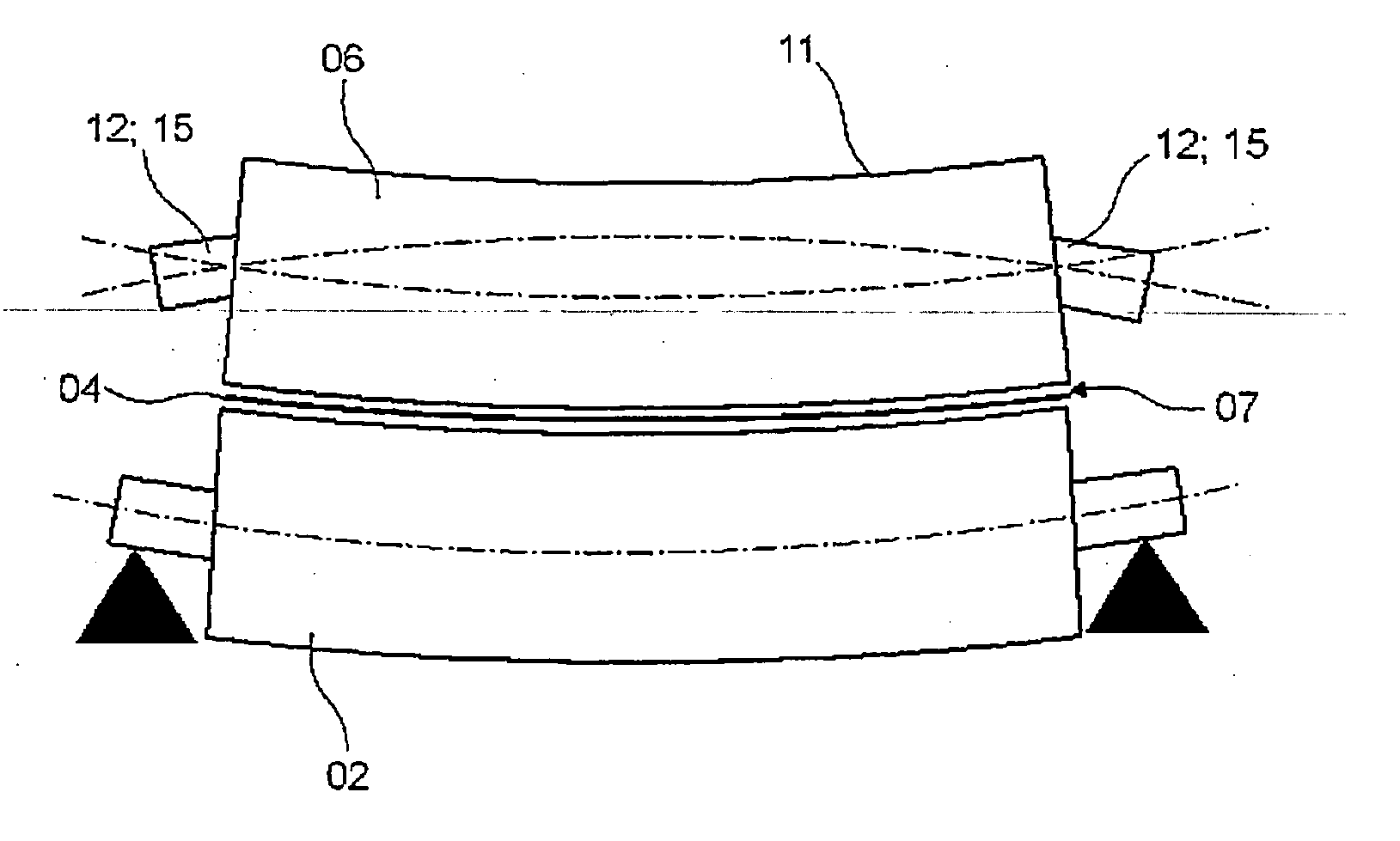
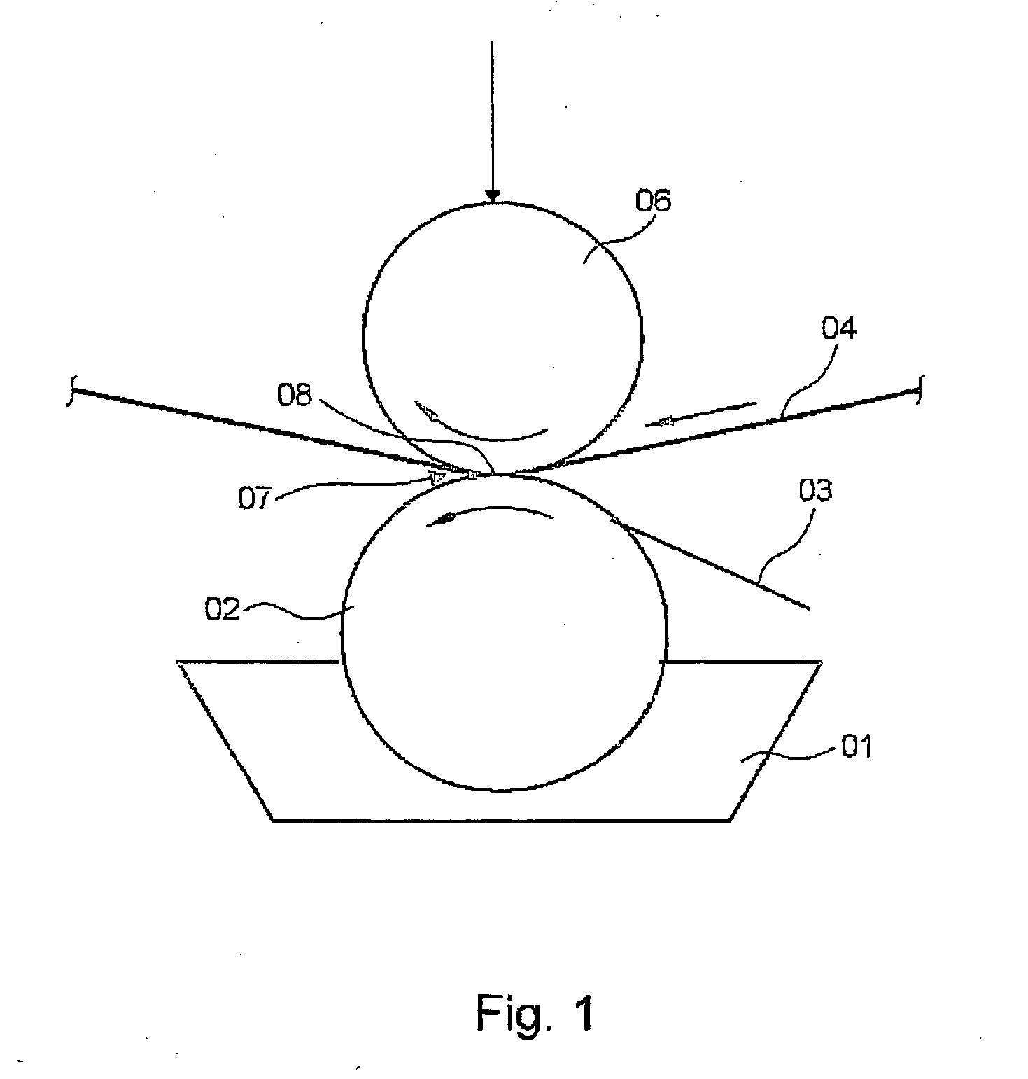
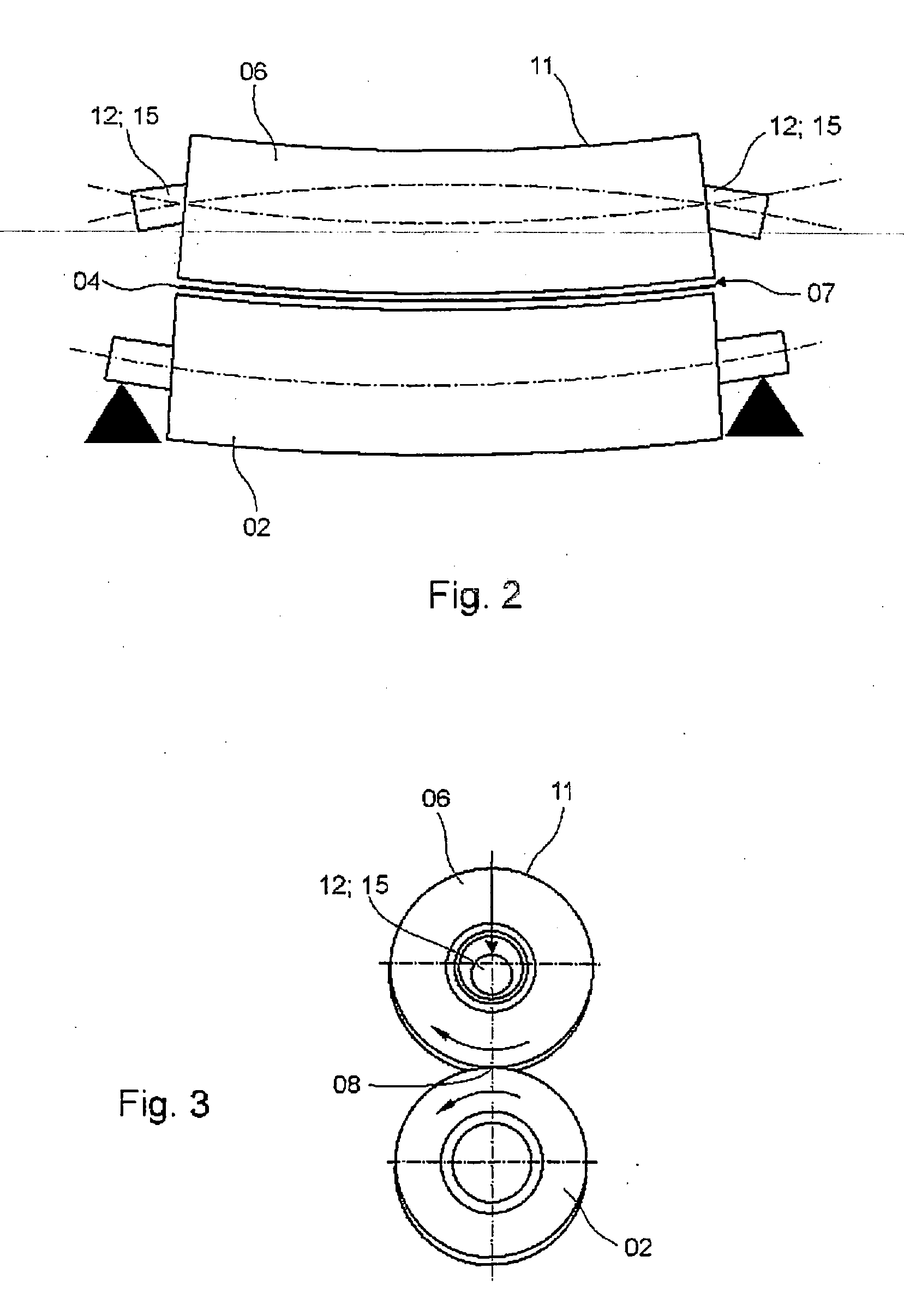
[0053] A printing group, which is generally known per se, of a rotogravure printing press, is schematically represented in a side elevation view in FIG. 1. This generally known group consists of a first cylinder 06 and a second cylinder 02, which define a cylinder gap 07, through which a paper web 04 to be imprinted is conducted as the web 04 of material is clamped along a clamping line 08 which clamping line 08 extends perpendicularly with respect to the plane of FIG. 1. The second cylinder 02 is preferably provided with an engraved copper surface. The second cylinder 02 is a forme cylinder 02, which can be easily disassembled, and which is dipped into an ink reservoir 01. Forme cylinder 02 is seated, in a manner not specifically represented, but which is known per se, in a frame, that is not specifically represented in FIG. 1, and is connected with a drive mechanism. A doctor blade 03 for use in removing excess ink, which may be taken along by the forme cylinder 02 from the ink re...


PUM


Abstract

Please add the Abstract of the Disclosure which is set forth on the separate accompanying sheet. That Abstract of the Disclosure is essentially the same, in content, as the Abstract which is a part of the published PCT application WO 2004 / 085155. No new matter is being added by the presentation of the Abstract of the Disclosure.

Description

CROSS-REFERENCE TO RELATED APPLICATIONS [0001] This application is the U.S. National Phase, under 35 USC 371, of PCT / DE 2003 / 004237, filed Dec. 22, 2003; published as WO 2004 / 085155 A1 on Oct. 7, 2004 and claiming priority to DE 103 13 444.1 filed Mar. 26, 2003, the disclosures of which are expressly incorporated herein by reference.FIELD OF THE INVENTION [0002] The present invention is directed to a cylinder, as well as to a device for guiding a web of material. The cylinder is bent with respect to the web travel direction in response to an image of the web. BACKGROUND OF THE INVENTION [0003] Pairs of cylinders are frequently employed as tools for guiding webs of material, or for processing their surfaces. The cylinders are rotatably arranged with pivotable shafts and delimit a gap through which the web of material runs. Along a clamping line which is parallel with the shafts, the web is subjected to a pressure from a cylinder which pressure exerts a guiding pressure or effect on t...

Claims


Application Information

Patent Timeline
Patent Type & Authority Applications(United States)
IPC IPC(8): B41F13/187
CPCB41F13/187
Inventor RIEDEL, UWE JOHANN
Owner OFFICINE MECCANICHE GIOVANNI CERUTTI
Learn More