
Control apparatus for internal combustion engine

Inactive Publication Date: 2005-09-08
TOYOTA JIDOSHA KK
View PDF65 Cites 3 Cited by
  • Summary
  • Abstract
  • Description
  • Claims
  • Application Information

AI Technical Summary

Benefits of technology

[0011] To solve the problems as described above, an object of the present invention is to provide a control apparatus for an internal combustion engine to enhance the drivability through a proper purging treatment of vaporized fuel and to suppress the fluctuation in rotation in the idling operation state.
[0013] According to the control apparatus for the internal combustion engine of the present invention, since the amount of power generated by the electric generator is controlled to be higher when the vapor concentration of the vaporized fuel is high compared with when the vapor concentration is low if the purge execution condition is met in the idling operation state of the internal combustion engine, the power generation friction of the electric generator becomes constant and the fluctuation in rotation of the internal combustion engine can be suppressed and the proper purging treatment of the vaporized fuel can be achieved whereby the drivability can be enhanced.

Problems solved by technology

In an idling operation state of the internal combustion engine, however, such a control makes an actual amount of fuel injection excessively low since the amount of fuel injection is low in the idling operation state because of a low pressure even without the controlled decrease of fuel injection in accordance with the amount to be treated.
When the amount of fuel injection is excessively low, stability of combustion is negatively affected to lower efficiency of emission purification or to functionally disable an injection by a fuel injector.
Thus in the idling operation state, because of the small margin of the fuel injection amount, the vaporized fuel treatment unit cannot properly perform the purging treatment of a predetermined amount of vaporized fuel collected in the canister.
Hence, when the power generation friction of the alternator varies, the generated torque in the internal combustion engine, therefore, the amount of air intake and the amount of fuel injection fluctuate to cause the fluctuation in rotation of the internal combustion engine, thereby deteriorating the drivability.
When the amount of air intake and the amount of fuel injection vary in the idling operation state of the internal combustion engine, the vaporized fuel treatment unit cannot properly purge the vaporized fuel collected in the canister to the intake path thereby preventing the secure treatment of the vaporized fuel.

Method used


Image

  • Control apparatus for internal combustion engine
  • Control apparatus for internal combustion engine
  • Control apparatus for internal combustion engine

Examples


Embodiment Construction

[0020] In the following, an embodiment of a control apparatus for an internal combustion engine according to the present invention will be described in detail with reference to the drawings. Note that the present invention is not limited to the embodiment.

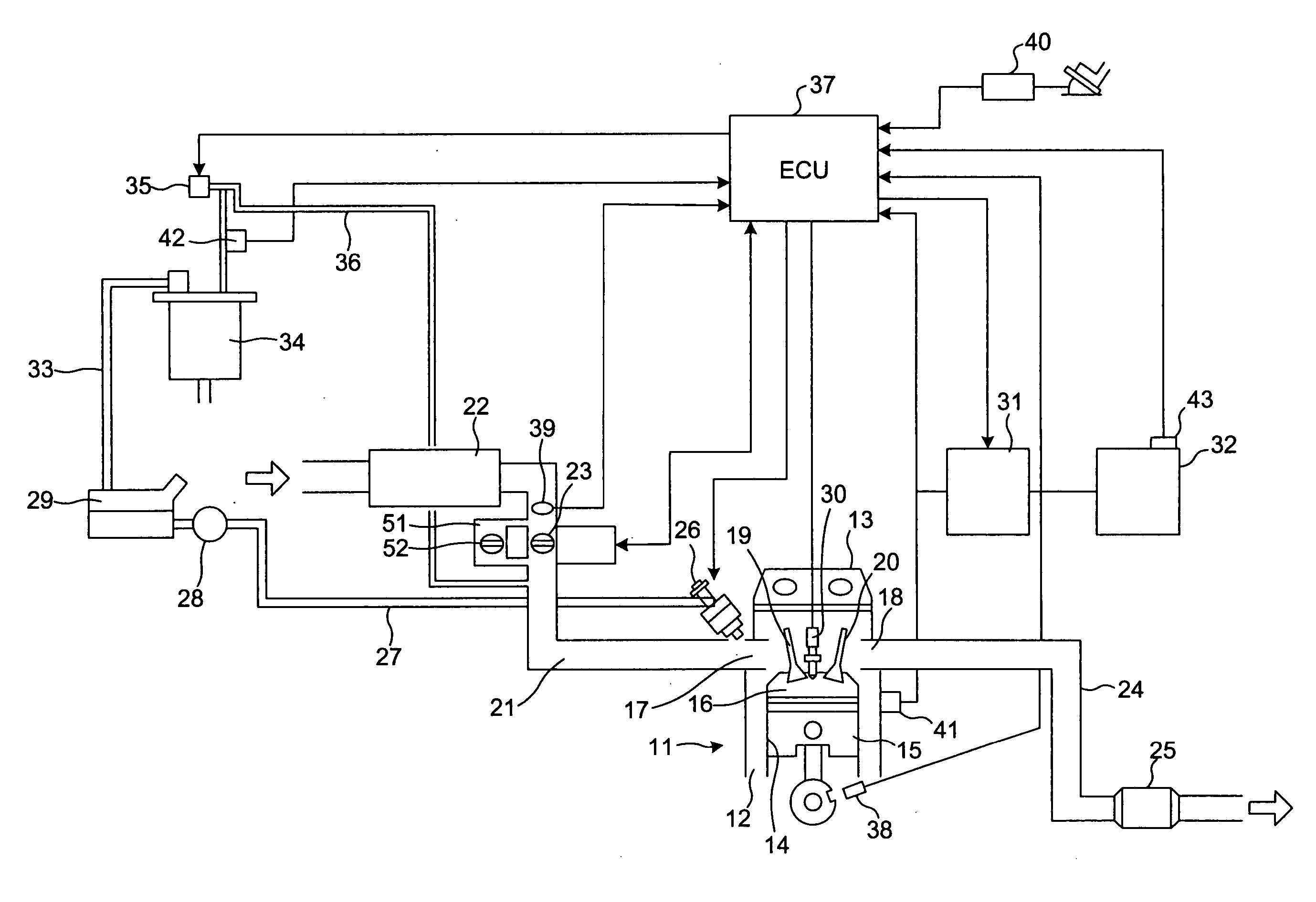
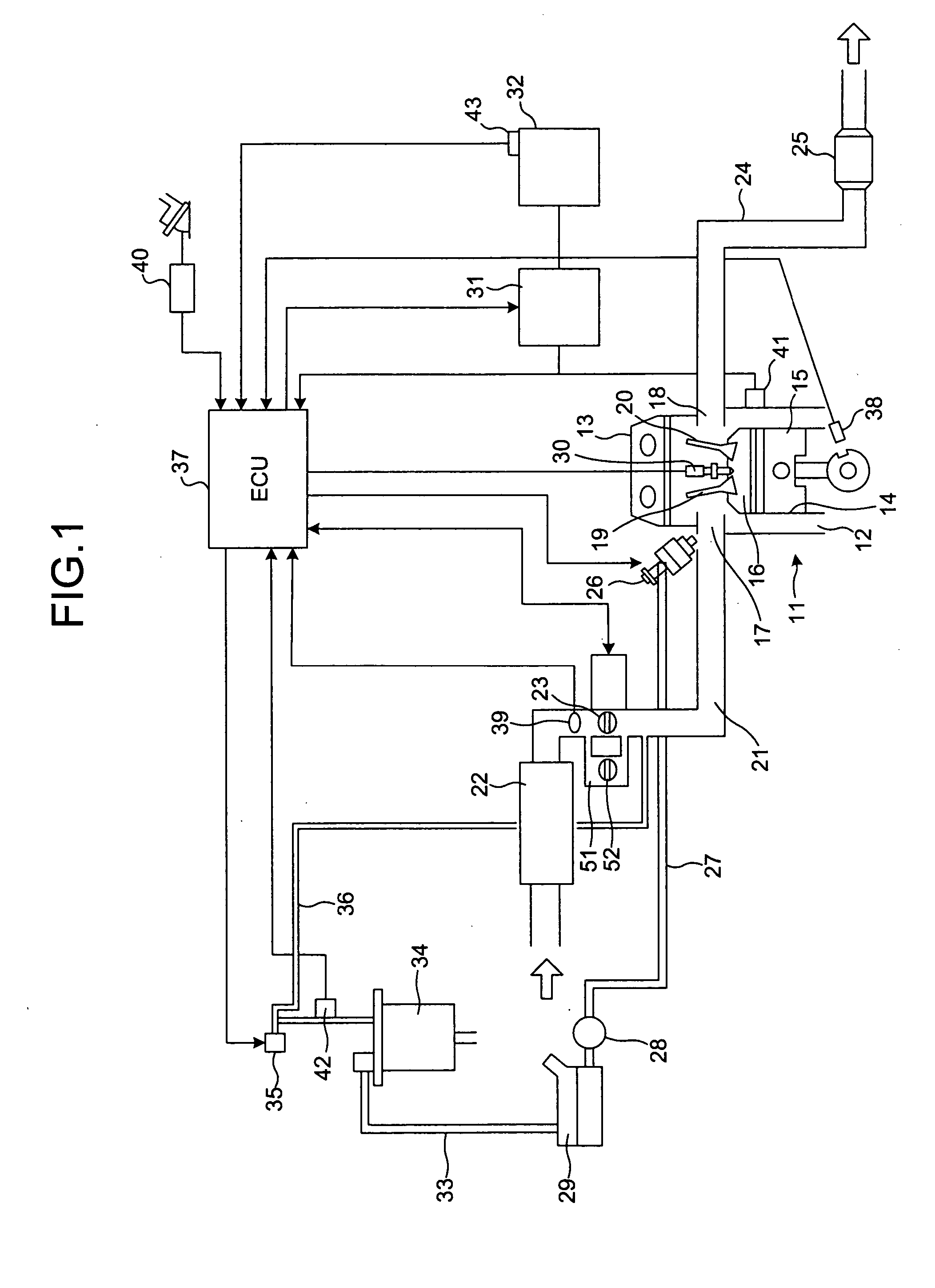
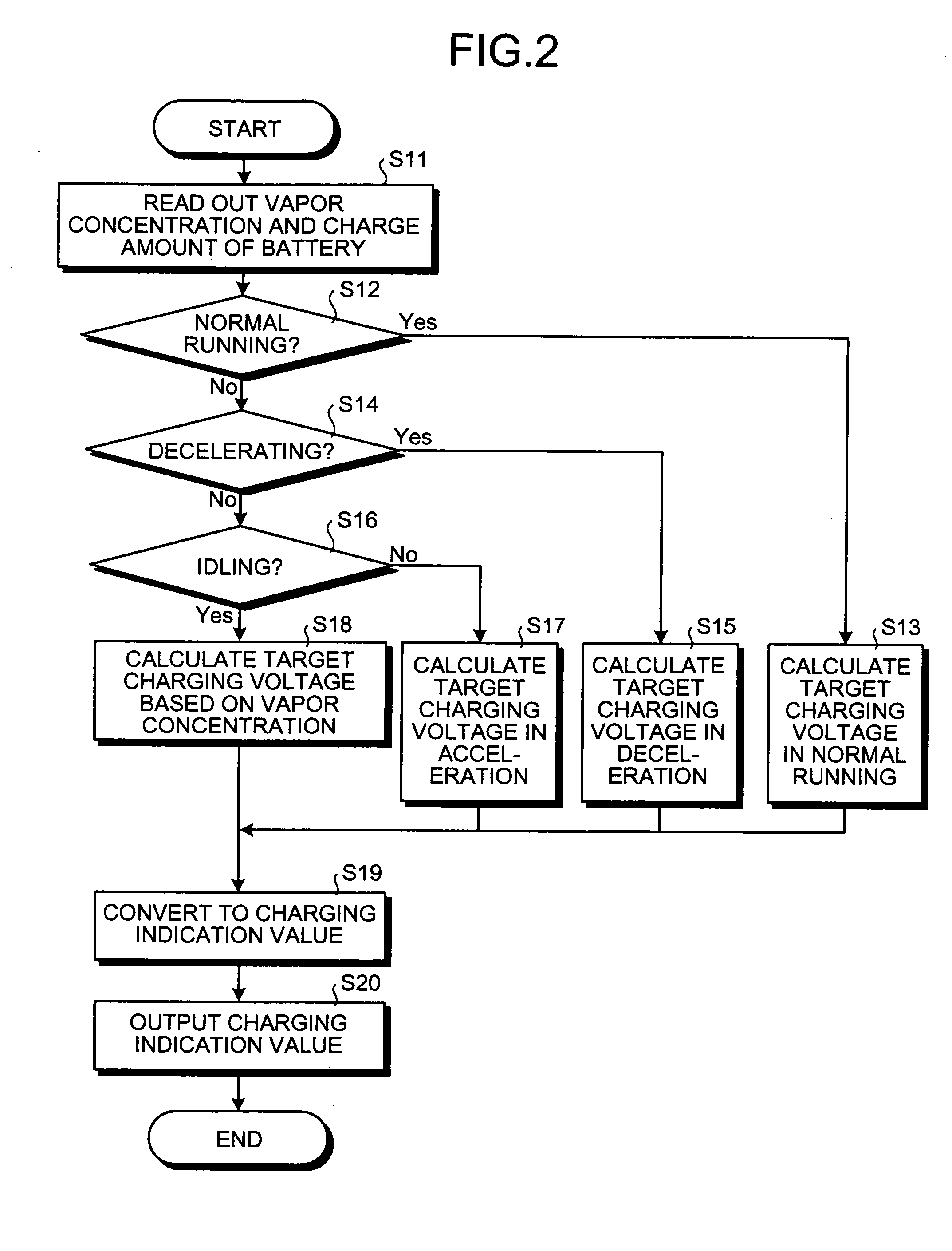
[0021]FIG. 1 is a schematic diagram of a control apparatus for an internal combustion engine according to the embodiment of the present invention, FIG. 2 is a flowchart of a charging control by the control apparatus for the internal combustion engine of the embodiment, FIG. 3 is a flowchart of a purging control by the control apparatus for the internal combustion engine of the embodiment, and FIG. 4 is a graph showing a relation between fuel vapor concentrations and target charging voltages in the control apparatus for the internal combustion engine of the embodiment.

[0022] In the control apparatus for the internal combustion engine of the embodiment, as shown in FIG. 1, an engine 11 is a gasoline engine of a spark ignition type....


PUM


Abstract

In a control apparatus for an internal combustion engine, an amount of electricity to be generated by an alternator (a target charging voltage) is set based on a vapor concentration of vaporized fuel when a purge execution condition is met for purging the vaporized fuel collected by a canister, whereby a fluctuation in rotation in an idling operation state is suppressed, an appropriate purging treatment of the vaporized fuel is allowed, and the drivability is improved.

Description

BACKGROUND OF THE INVENTION [0001] 1. Field of the Invention [0002] The present invention relates to a control apparatus for an internal combustion engine which controls an amount of power generated by an electric generator mounted in the internal combustion engine, and in particular to such a control apparatus which allows a secure purging of vaporized gas from a fuel tank together with a suppression of fluctuation in rotation of the internal combustion engine. [0003] 2. Description of the Related Art [0004] An internal combustion engine incorporates a vaporized fuel treatment unit which serves to treat the vaporized fuel generated in a fuel tank without emitting the vaporized fuel into the atmosphere. The vaporized fuel treatment unit includes a canister to collect the vaporized fuel from the fuel tank. The vaporized fuel is temporarily absorbed by an absorbent in the canister, and during the operation of the internal combustion engine, the vaporized fuel treatment unit purges a f...

Claims


Application Information

Patent Timeline
IPC IPC(8): F02D29/06F02M25/08F02D45/00
CPCF02D41/003
Inventor KANAI, HIROSHI
Owner TOYOTA JIDOSHA KK
Learn More