
Fastening system

a technology of fastening and clipping, applied in the direction of scarves, identification means, instruments, etc., can solve the problems that the use of a hair clip device for securement of planar objects, such as business or identification cards, cannot be achieved by any of the above structures, or otherwise, taught in the prior art, and achieve the effect of improving the hair clip

Inactive Publication Date: 2005-09-08
GOULD SHELDON D
View PDF13 Cites 12 Cited by
  • Summary
  • Abstract
  • Description
  • Claims
  • Application Information

AI Technical Summary

Benefits of technology

[0012] It is a further object to provide an improved hair clip.

Problems solved by technology

However, use of a hair clip device for securement of planar articles, such as business or identification cards, cannot be achieved by any of the above structures, or otherwise, taught in the prior art.

Method used


Image

  • Fastening system
  • Fastening system
  • Fastening system

Examples


embodiment 100

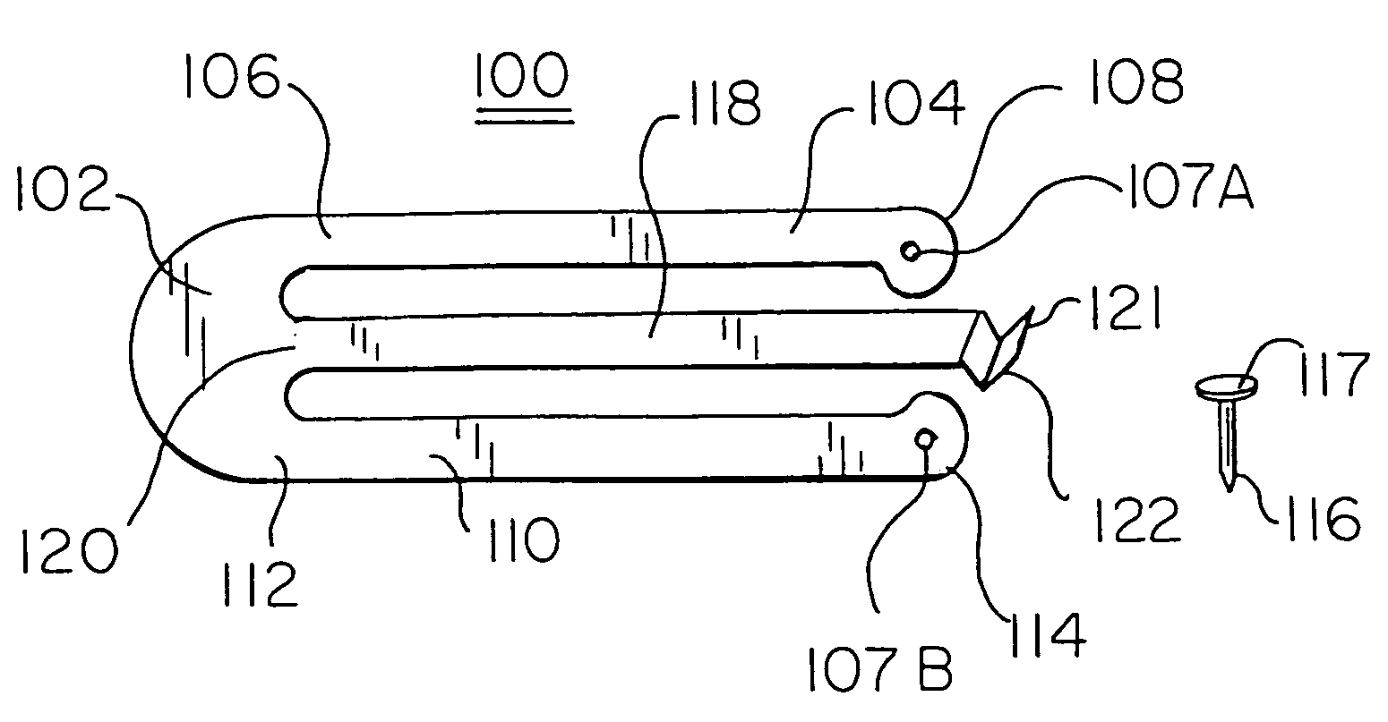
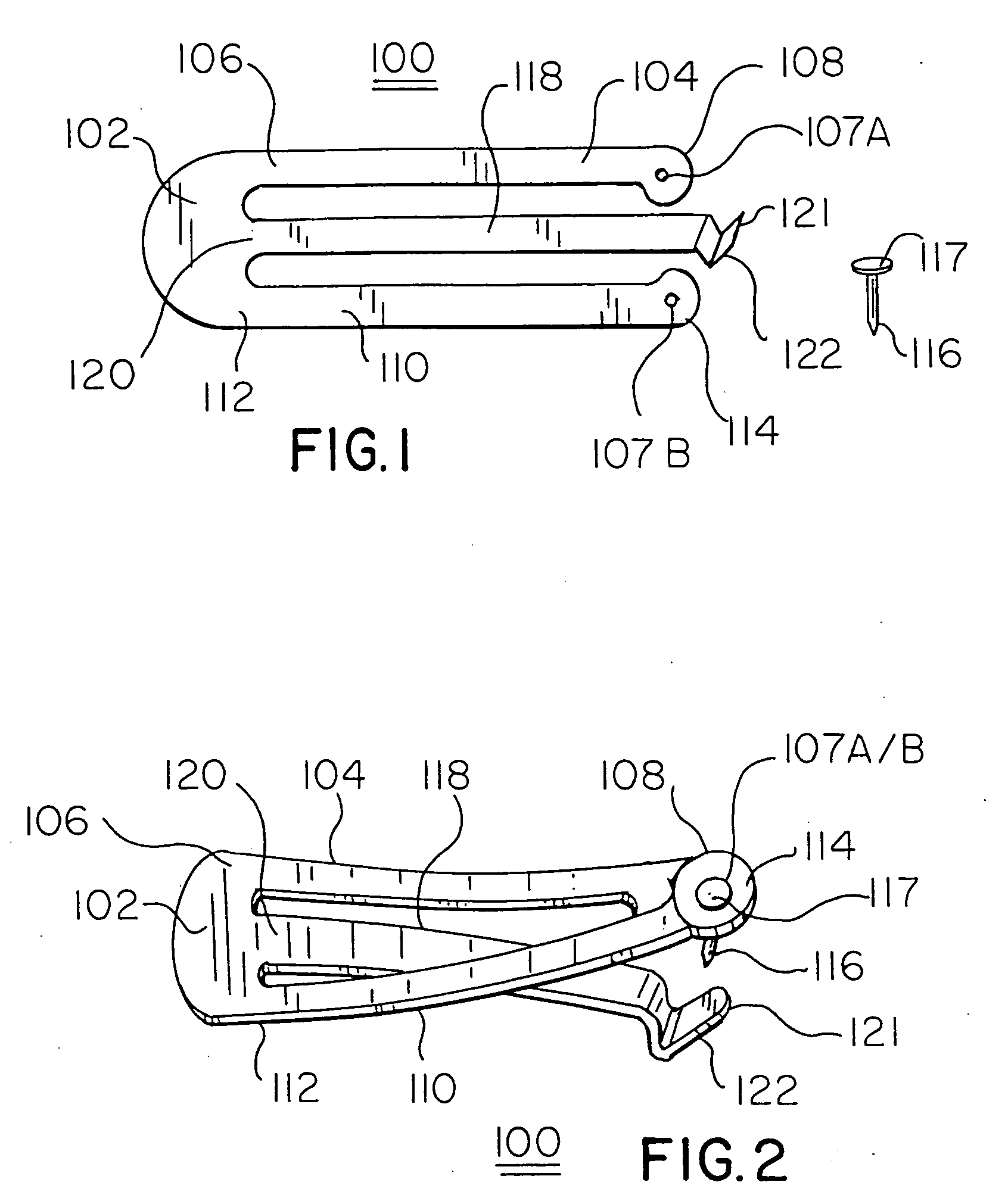
[0024]FIG. 2 is an operational view of the embodiment 100 of the fastening system of FIG. 1. Therein, distal end 114 of second leg 110 is shown in alignment with distal end 108 of leg 104, so that apertures 107A and 107B are in alignment. When in this position, straight pin 116 may be passed therethrough such that head 117 of pin 116 is visible. When in this position, female surface 122 of distal end 121 is aligned beneath the point of straight pin 116, such that engagement therebetween can be manually effected in the manner shown in FIG. 11. Also shown in FIG. 2 is the flexible nature of legs 104 and 110 of the fastening system. The resultant structure of FIG. 2 is one in which a planar article such as a business or identification card may be secured between pin head 117 and female surface 122 when base 122 is appropriately secured to clothing of a user of the system.

[0025] Shown in FIG. 3 is a second embodiment 300 of the inventive fastening system in which pin 316 depends from a ...

embodiment 500

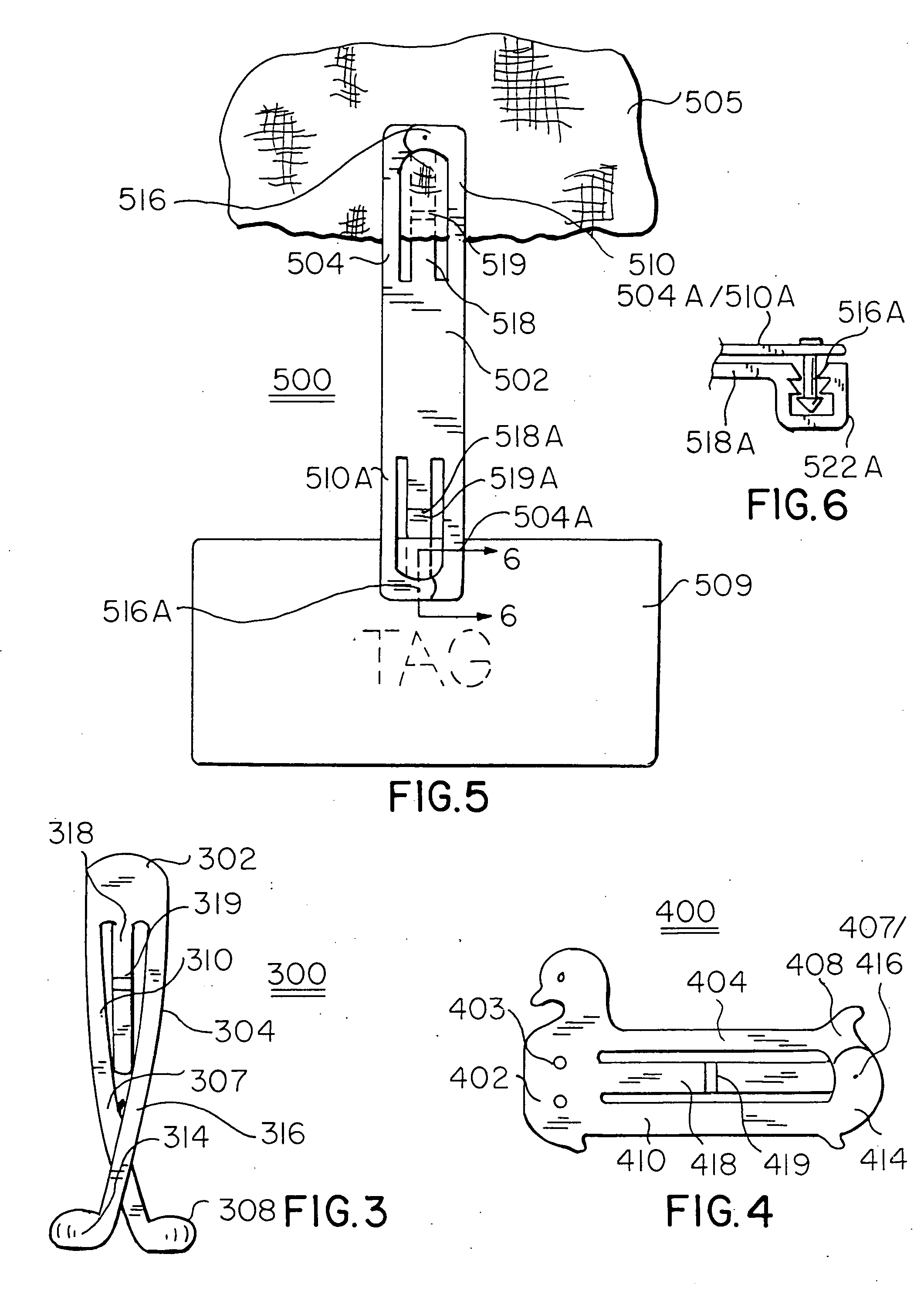
[0027] In the embodiment 500 of FIG. 5 is shown a still further embodiment in which a fastening system 500 includes a central base region 502 from which depends symmetric upper and lower sets of arms, namely, upper arms 504 and 510, and lower arms 504A and 510A. Therein are also shown elongate securement legs 518 and 518A from which depend female engagement surfaces 522 (not shown) and 522A (see FIG. 6). As in the case of the embodiment of FIGS. 3 and 4, there are provided flexure zones 519 and 519A respectively to permit appropriate bending of securement legs 518 and 518A when the system is secured to fabric 505 and / or planar tag 509.

[0028] The pin-female surface interface 516A / 522A is shown in vertical axial cross-sectional view in FIG. 6.

[0029] With reference to FIGS. 7 thru 13, there is shown another embodiment 600 of the inventive fastening system which includes an elongate securement leg 618 which integrally depends from a base 602 having line of dependency 617. Also dependen...


PUM


Abstract

A fastening system includes a straight pin having a cap end, a shank and a pointed end; a planar border having a base and two integrally formed substantially parallel planar flexible peripheral legs of like length, distal ends of each of the legs having apertures proportioned for slidable receipt of the shank of the straight pin; and an elongate securement leg integrally dependant from the base in a direction of the distal ends of the flexible legs, a distal end of the securement leg including a female surface press-fittably complemental about the pointed end of the straight pin. The pin may be inserted through the apertures when they are aligned with each other, and then held by the female surface to enable securement of a planar peripheral legs to each other.

Description

REFERENCE TO RELATED APPLICATION [0001] This Application corresponds to the subject matter of Disclosure Document No. 522,261, filed Nov. 25, 2002.BACKGROUND OF THE INVENTION [0002] The present invention relates to devices in the nature of hair clips which, subject to adaptations as taught by the within invention, may be employed as a fastening element for the holding of cards and other planar articles. [0003] The prior art in the instant area is reflected in hair clip related patents such as U.S. Pat. No. 2,169,940 (1939) to Polak; U.S. Pat. No. 2,795,233 (1957) to Zore, entitled Clips; U.S. Pat. No. 3,082,773 (1963) to Renstrom, et al, entitled Hair Clip; and U.S. Pat. No. 3,860,014 (1975) to Clifton, entitled Hair Clip. [0004] Said patent to Polak teaches a hair clip in which a male element thereof may be secured within a female element to accomplish closure of the clip about a tuft of hair. [0005] Zore teaches a hair clip including a fixed proximal end and a free distal end. The...

Claims


Application Information

Patent Timeline
Patent Type & Authority Applications(United States)
IPC IPC(8): A44B9/12A44B99/00A45D8/22A45D8/28
CPCA45D8/16A45F5/02A45F2200/055G09F3/16Y10T24/4664Y10T24/3476Y10T24/1365Y10T24/44906Y10T24/346G09F3/207
Inventor GOULD, SHELDON
Owner GOULD SHELDON D
Learn More