
Server allocation control method

a server and control method technology, applied in the field of server allocation control method, can solve the problems of poor server operation rate, inability to achieve effective server application, and inability to guarantee service levels of fixed standard or better

Inactive Publication Date: 2005-09-01
FUJITSU LTD
View PDF2 Cites 198 Cited by
  • Summary
  • Abstract
  • Description
  • Claims
  • Application Information

AI Technical Summary

Benefits of technology

[0013] According to a more preferred embodiment in the first aspect of the invention, the method further includes: finding a third average response time per server of the plurality of servers included in a new server group following the addition of the selected server; performing a new determination whether the third average response time is within the range; and selecting one of the servers of the unused server group if the result for the third average response time of the new determination is not within the range. And the finding a third average response time, the performing a new determination and the selecting are repeated and the server belonging to the unused server groups is added one-by-one to the server group until the result for the third average response time of the new determination is within the range.
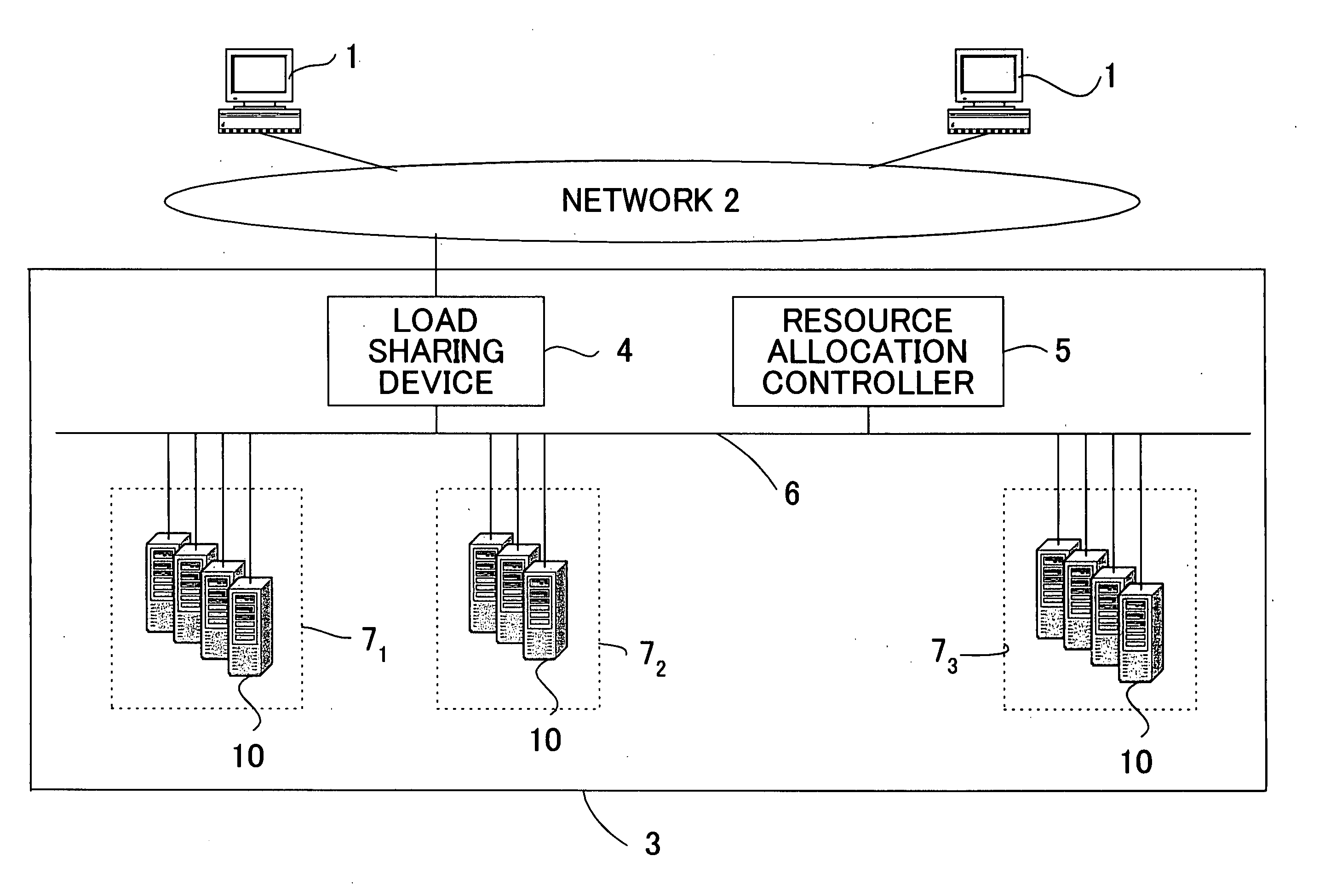
[0014] Further, as a second aspect, the abovementioned object is achieved by providing a program for a resource allocation controller connected to a network in a network system which includes a plurality of user terminals connected to the network, server groups each containing a plurality of servers connected to the network to process requests from the user terminals and a load sharing device connected to the network involving a storage storing the number of requests from the user terminal for prescribed time intervals, a distribution rate of the number of requests and a configuration information of the server groups. The program causes the resource allocation controller to execute the method including: finding a function to describe a characteristic between time and the number of requests on the basis of a previous stored number of requests stored in the load sharing device; predicting the number of future requests by substituting a future time for the function; obtaining a first average response time per server of the plurality of servers by substituting the predicted number of requests in a relational expression of the number of requests and an average response time per server of the plurality of servers where it is hypothesized that the number of requests from the plurality of user terminals follows a prescribed probability distribution; determining whether the first average response time is a positive value and within a range no more than a threshold value set in advance, and increasing or decreasing the number of servers contained in the server group in accordance with the result of the determination.
[0015] According to a more preferred embodiment in the second asp

Problems solved by technology

When there are too many servers allocated to a network service the operation rate of the servers is poor and the effective application of the servers is unachievable.
Conversely, when there are too few servers, service levels of a fixed standard or better cannot be guaranteed.
However, using the methods of the prior art in which, because the load on the network services fluctuates frequently depending on, for example, time slot, seasonal factors and artificial factors, and these fluctuations are different for each network service, the settings of the load sharing device are set manually, it is difficult for these fluctuation patterns to be predicted based solely on the experience and judgment of an operations manager.
In addition, although the methods of the prior art facilitate the automatic setting of the load sharing device in real time without need for an operator, they do not provide a means for adjudging whether or not more servers will be required in the future or whether a lesser number is sufficient.
Accordingly, an inherent problem therewith is that the number of servers allocated in accordance with the existing operating conditions will not necessarily form the optimum number of servers for operating conditions that will exist in the future.

Method used


Image

  • Server allocation control method
  • Server allocation control method
  • Server allocation control method

Examples


Embodiment Construction

[0030] A description of an embodiment of the present invention is given below with reference to the diagrams. However, the technical range of the present invention is in no way restricted to this embodiment.

[0031] The sequence of the explanation of the embodiment of the present invention will be of an example configuration of an entire system in the embodiment, an example configuration of the devices of the abovementioned system, example data configuration stored in the devices of the abovementioned system, and the operational flow for explaining a method of the present invention. First, an explanation will be given of an example configuration of the entire system in the embodiment.

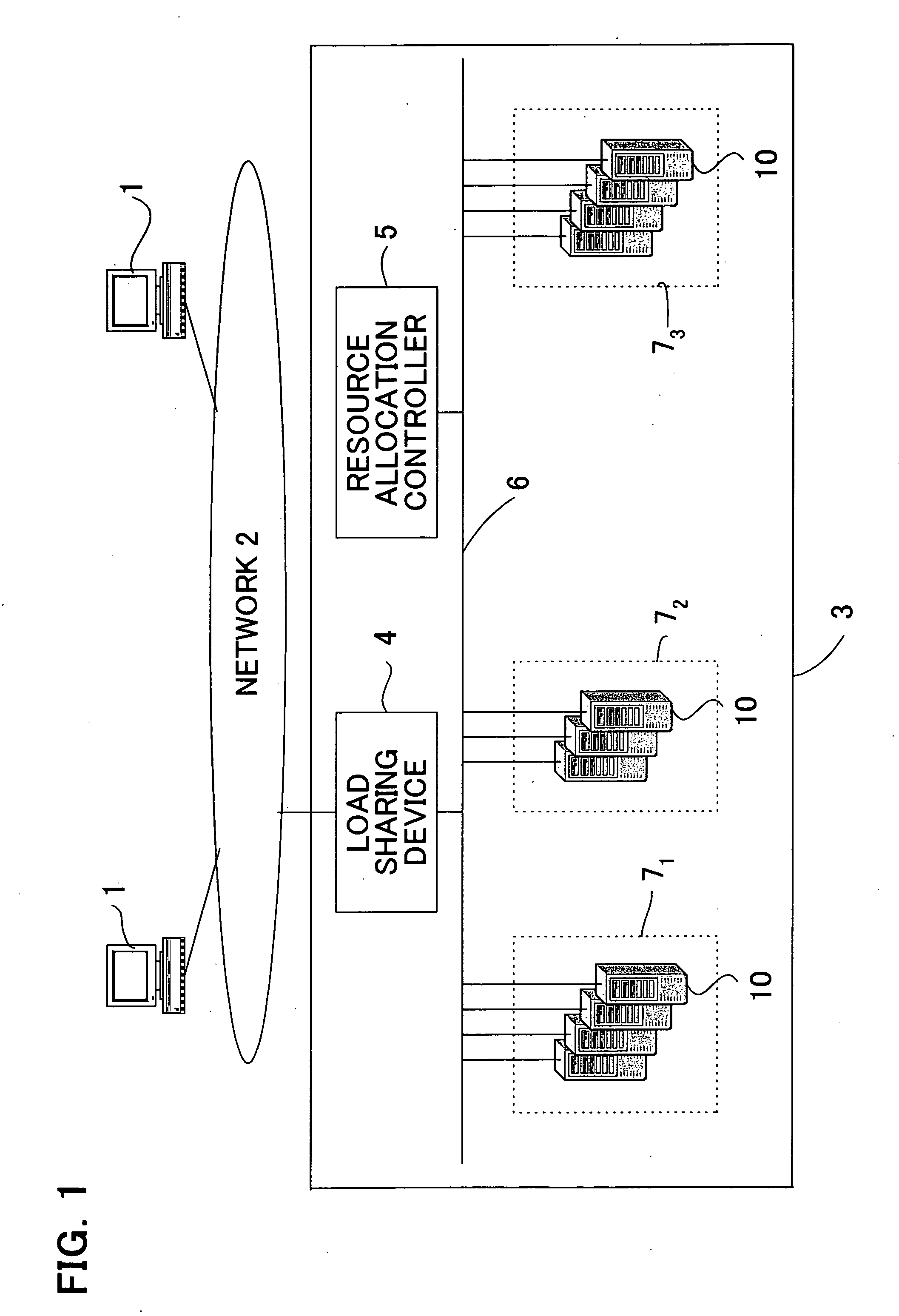
[0032]FIG. 1 is a diagram for explaining an example configuration of the entire system of one embodiment of the present invention. For the purpose of simplification of the description, all servers providing the network services of the embodiment of the present invention have been assumed to be servers o...


PUM


Abstract

A method to automatically allocate servers to network services in a data center in real time and without need for operators for a load sharing device is provided. In the method, fluctuations in quantity of requests arriving at the network services can be monitored, the value of the quantity of requests for a subsequent fixed time interval can be predicted and, in accordance with the magnitude of the predicted value of the quantity of requests, the quantity of servers allocated to the network services can be controlled. Here, where traffic of the quantity indicated by the predicted value of the quantity of requests arrives at the network services, the number of servers allocated to the network services can be set in such a way that the average response time to the user terminals is equivalent to a response time threshold value or less set in advance by the operations manager.

Description

TECHNICAL FIELD [0001] The present invention relates to a method for dynamically altering the configuration of server groups allocated to network services to ensure that a fixed standard response time is achieved by a plurality of servers providing said network services. BACKGROUND ART [0002] A diversity of network services is currently provided by way of networks such as the Internet. Some of the so-called service providers (xSP), which are companies that provide network services including Internet Service Providers (ISP) and Application Service Providers (ASP) and so on, do not perform the in-house support and management of the servers that provided the network services and instead engage a data center to perform these tasks. [0003] The data center has, in an in-house data center, a plurality of servers of which parts thereof are allocated for each network service. That is to say, server groups composed of a plurality of servers exist for each network service, and service requests...

Claims


Application Information

Patent Timeline
IPC IPC(8): G06F9/46G06F9/50G06F15/173H04L29/08
CPCG06F9/5083H04L67/1008G06F2209/5022H04L67/1012G06F2209/5019H04L67/1002H04L67/1001
Inventor KOKUSHO, YASUHIROTUTIYA, SATOSHIKAWAI, TSUTOMU
Owner FUJITSU LTD
Learn More