
Providing a portion of an electronic mail message based upon a transfer rate and a message size

a technology of electronic mail and transfer rate, applied in the field of electronic mail messaging, can solve the problems of increasing the complexity and size affecting the delivery of electronic mail messages, and limiting the number of electronic mail messages

Inactive Publication Date: 2005-09-01
IBM CORP
View PDF53 Cites 47 Cited by
  • Summary
  • Abstract
  • Description
  • Claims
  • Application Information

AI Technical Summary

Benefits of technology

The patent describes a method for selecting a portion of an email message based on the transfer rate and size of the message. This allows for faster and more efficient email communication. An apparatus and article containing instructions for implementing this method are also provided. The technical effect of this patent is improved efficiency and speed in email communication.

Problems solved by technology

The complexity and size of electronic mail messages has increased roughly in proportion with the available transfer rate.
Early electronic mail message systems relied upon comparatively slow modems and thus these electronic mail messages were typically limited to short ASCII text documents.
Despite the advantages of using high-speed connections to transmit large information-rich electronic mail messages, the same messages can become problematic when they must be transmitted by a lower speed connection.
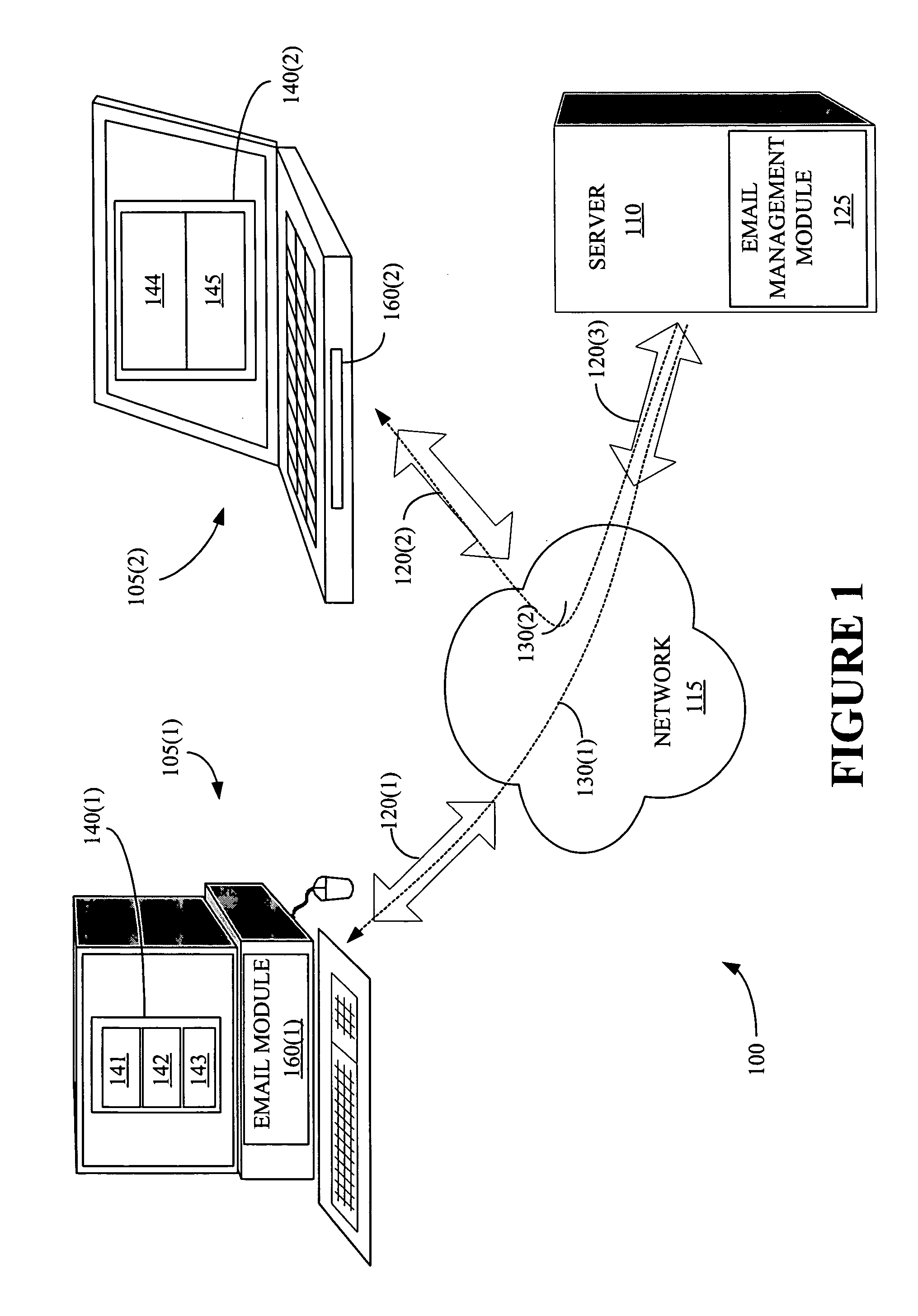
As another example, a user writing electronic messages on the laptop computer connected to the Internet via a 14.4 Kbps (K bits per second) dial-up modem may want to attach a large document to an electronic mail message, but may have to wait an unreasonable amount of time for the electronic mail message to be uploaded through the modem.
In addition, bottlenecks, heavy traffic, device malfunctions, severed transmission lines, geomagnetic storms, and the like can dramatically, and often unpredictably, decrease the transfer rate of even the highest speed networks.

Method used


Image

  • Providing a portion of an electronic mail message based upon a transfer rate and a message size
  • Providing a portion of an electronic mail message based upon a transfer rate and a message size
  • Providing a portion of an electronic mail message based upon a transfer rate and a message size

Examples


Embodiment Construction

[0019] Illustrative embodiments of the invention are described below. In the interest of clarity, not all features of an actual implementation are described in this specification. It will of course be appreciated that in the development of any such actual embodiment, numerous implementation-specific decisions must be made to achieve the developers' specific goals, such as compliance with system-related and business-related constraints, which will vary from one implementation to another. Moreover, it will be appreciated that such a development effort might be complex and time-consuming, but would nevertheless be a routine undertaking for those of ordinary skill in the art having the benefit of this disclosure.

[0020] The words and phrases used herein should be understood and interpreted to have a meaning consistent with the understanding of those words and phrases by those skilled in the relevant art. No special definition of a term or phrase, i.e. a definition that is different from...


PUM


Abstract

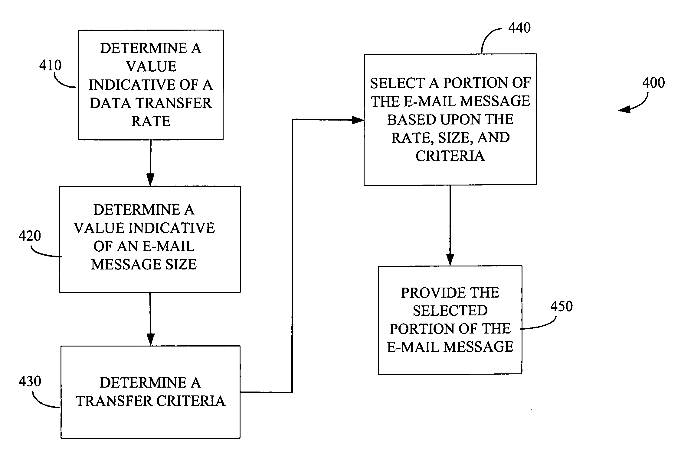
A method and an apparatus for providing a portion of an electronic mail message based upon a transfer rate and a message size are presented. The method includes determining a value associated with a data transfer rate, determining a value associated with a size of an electronic mail message, and determining mail transfer criteria. The method also includes selecting a portion of the electronic mail message based upon the determined transfer rate value, the determined value associated with the size of the electronic mail message, and the determined mail transfer criteria. The method further includes providing the selected portion of the electronic mail message.

Description

BACKGROUND OF THE INVENTION [0001] 1. Field of the Invention [0002] This invention relates generally to electronic mail messaging, and, more particularly, to providing a portion of an electronic mail message based upon a transfer rate and a message size. [0003] 2. Description of the Related Art [0004] Electronic mail has become a central feature of modern life and users have come to expect to receive electronic mail messages at any time and in virtually any place. For example, during the course of one day of travel, a user may receive electronic mail messages at a home desktop computer in the early morning, an office desktop computer in midmorning, via a cell phone or personal digital assistant in a taxi on the way to the airport, on a laptop computer via a wireless local area network while waiting in the airport lounge, via an in-flight telephone on the airplane, and in a hotel room via a high-speed Internet connection provided by the hotel at the end of the day. [0005] Thus, depen...

Claims


Application Information

Patent Timeline
Patent Type & Authority Applications(United States)
IPC IPC(8): G06F15/16G06F15/173G06F17/30G06Q10/00H04L12/58
CPCG06Q10/107H04L51/08H04L51/066H04L12/5835
Inventor BROWN, MICHAEL W.PAOLINI, MICHAEL A.SMITH, NEWTON J.
Owner IBM CORP
Learn More