
Compression quick connect/disconnect rotating lug terminal

a terminal and lug technology, applied in the direction of coupling contact members, coupling device connections, electrical apparatus, etc., can solve the problem of limiting the bend radius, and achieve the effect of preventing accidental electrical grounding of the connector

Active Publication Date: 2005-09-01
THOMAS & BETTS INT INC
View PDF21 Cites 13 Cited by
  • Summary
  • Abstract
  • Description
  • Claims
  • Application Information

AI Technical Summary

Problems solved by technology

However, the physical characteristics of heavy gauge wires / cables limit the radius of the bend that can be made.
The drawback of these connectors is that they have a fixed orientation and can only accommodate wires / cables coming from a limited number of different directions.

Method used


Image

  • Compression quick connect/disconnect rotating lug terminal
  • Compression quick connect/disconnect rotating lug terminal
  • Compression quick connect/disconnect rotating lug terminal

Examples


Embodiment Construction

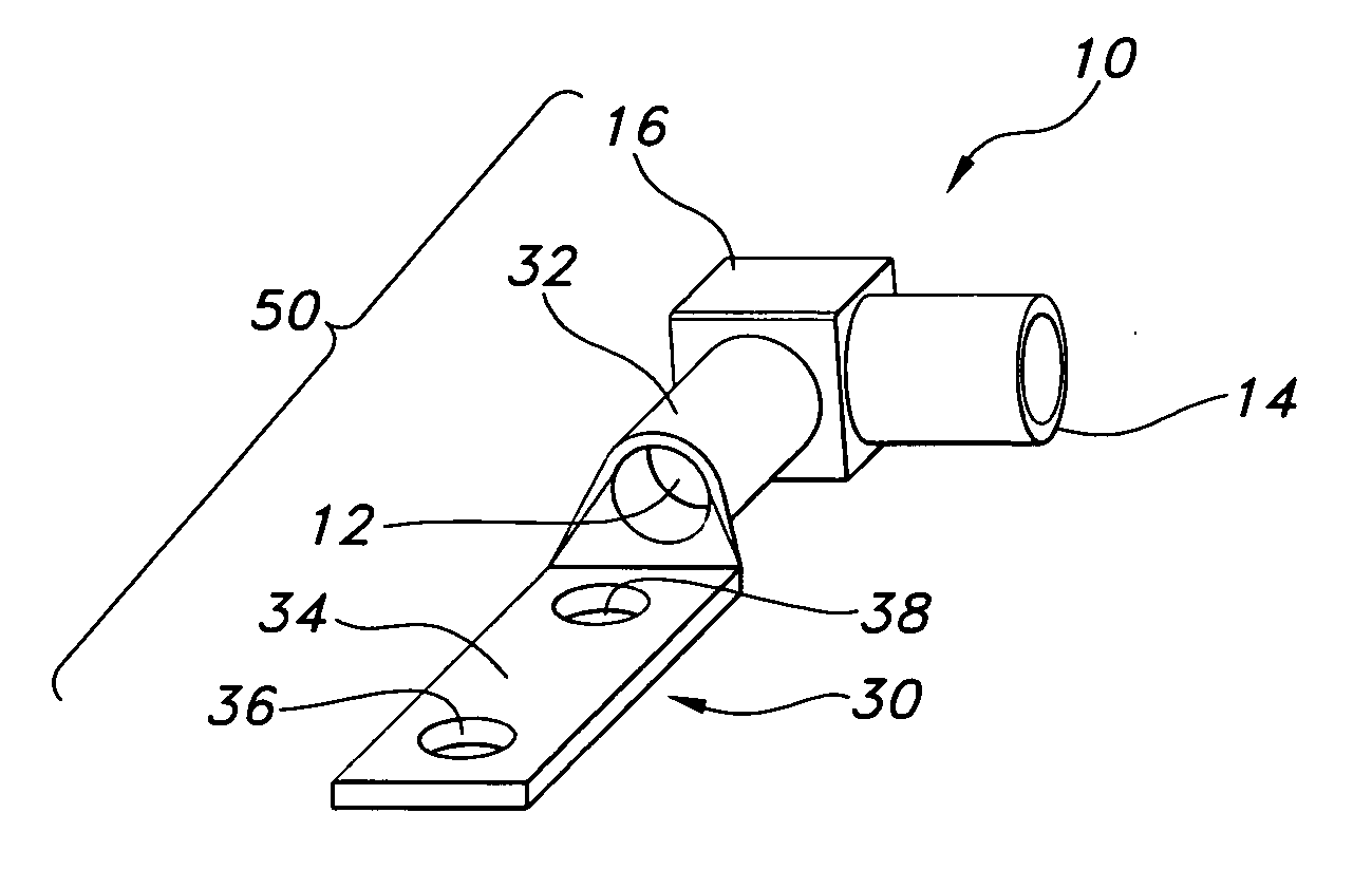
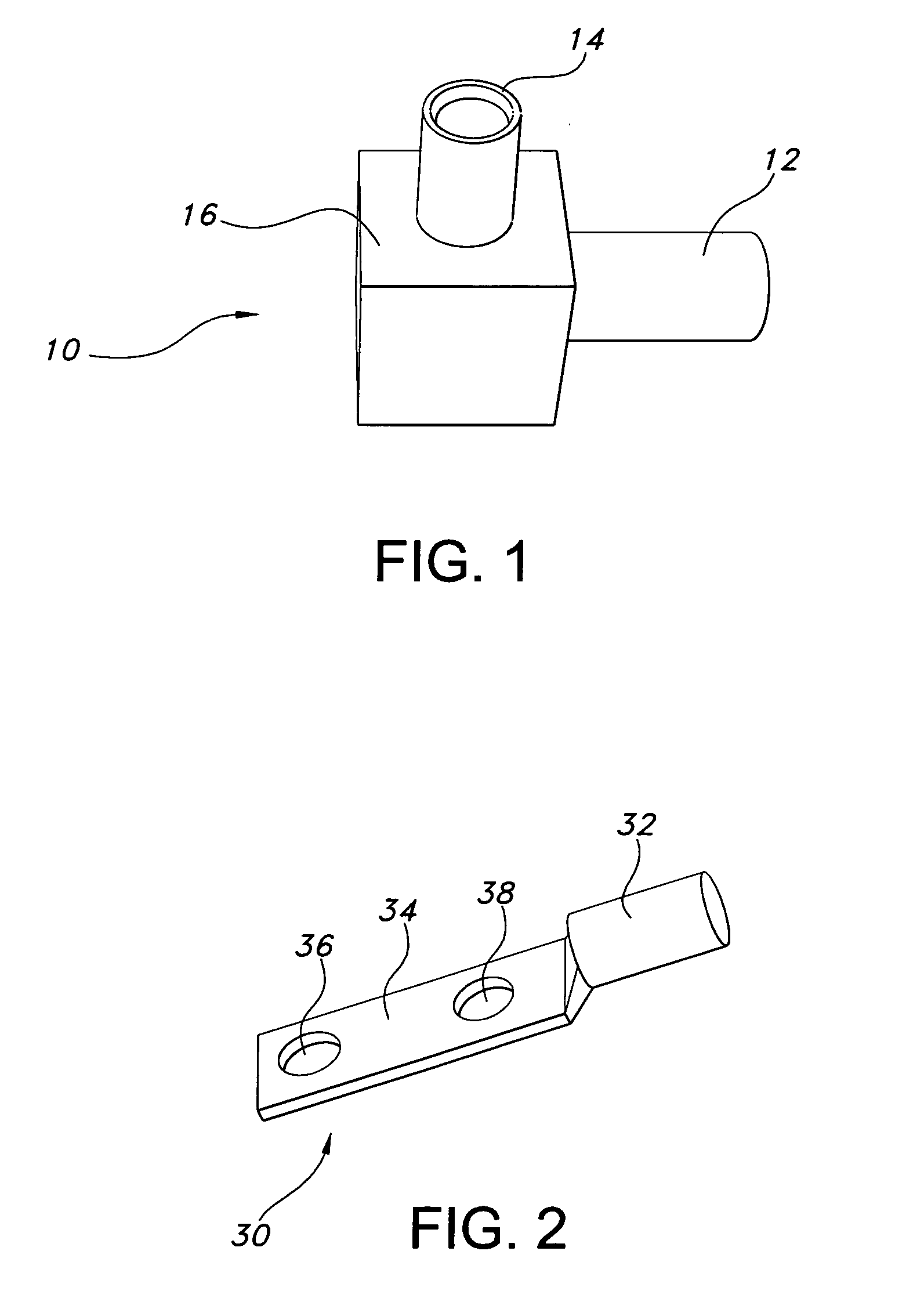
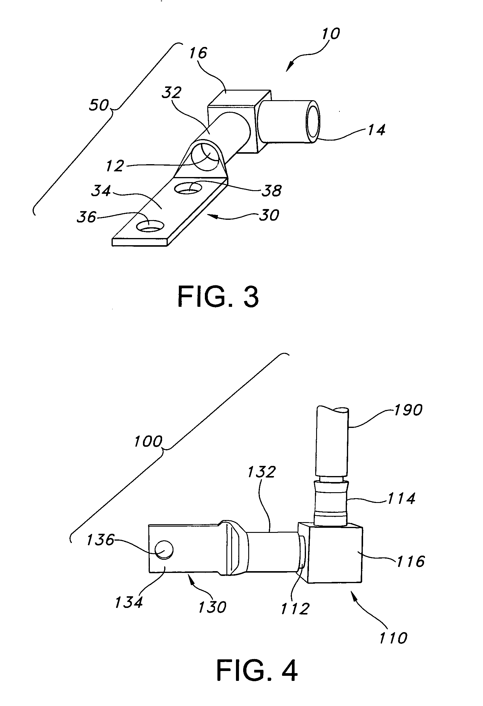
[0023] The connector assemblies of the present invention provide for easy and efficient connection of two or more wires / cables and are comprised of an angle connector, preferably with 90-degree or 180-degree connections, and at least one lug connector. The term lug connector is well know to those skilled in the art and refers to connectors that include a lug connection and a barrel-type compression fitting connection in various configurations. The connections for the angle connectors of the present invention can vary in size according to the size of the wires / cables that are being connected. The angle connectors have two or more connections which are preferably 90 degrees apart. In the most preferred embodiments, the angle connector has at least one connection which is a compression fitting connection. However, the angle connectors can have as many as six connections which can be made up of any combination of male pin connections and compression fitting connections.

[0024] The angle...


PUM


Abstract

An electrical connector assembly that includes a lug connector having a flat end with a flat end connector and a barreled end having a barrel connector and an angle connector that includes a body having a male pin and a compression fitting. The male pin is rotatably inserted into the barrel connector. After the orientation of the angle connector is selected, the barrel connector is compressed to mechanically and electrically engage the first male pin. The compression fittings of the angle connector can be sized to connect wires or cables from #8 AWG to 3000 kcmil in size. In preferred embodiments, the flat end and the barreled end of the lug connector are angularly disposed to each other and form an angle of between 60 and 150 degrees.

Description

[0001] This application claims priority from provisional application Ser. No. 60 / 548,751, filed on Feb. 27, 2004.BACKGROUND OF INVENTION [0002] The present invention relates to connectors for heavy gauge wires and cables that are used when a confined space does not easily allow the wires / cables to be bent. The angle connectors of the present invention combine angle connectors with a variety of different lug connectors to allow wire / cable bends to be made in various orientations when space is limited. [0003] When installing heavy gauge wires / cables, it is often necessary to bend the wires / cables to make a connection. However, the physical characteristics of heavy gauge wires / cables limit the radius of the bend that can be made. In some cases, lug connectors (also sometimes referred to as flag connectors) are used to make tight bends with heavy gauge wires / cables that cannot be easily bent. U.S. Pat. No. D302,542 to O'Loughlin and U.S. Pat. No. 4,771,538 to O'Loughlin et al. provide e...

Claims


Application Information

Patent Timeline
Patent Type & Authority Applications(United States)
IPC IPC(8): H01R11/12H01R13/04H01R25/00H01R27/02H01R43/16
CPCH01R11/12H01R43/16H01R13/04
Inventor WOODWARD, JERRY ALLEN
Owner THOMAS & BETTS INT INC
Learn More