
Graphics device clustering with PCI-express

a graphics device and clustering technology, applied in the field of computer graphics, can solve the problems of limiting the overall graphics performance of the cpu, the inability to provide additional gpus, and the difficulty of parallel rendering schemes, so as to facilitate the transfer of rendering commands and data, improve rendering performance, and saturate the processor bus

Active Publication Date: 2005-09-01
NVIDIA CORP
View PDF25 Cites 107 Cited by
  • Summary
  • Abstract
  • Description
  • Claims
  • Application Information

AI Technical Summary

Benefits of technology

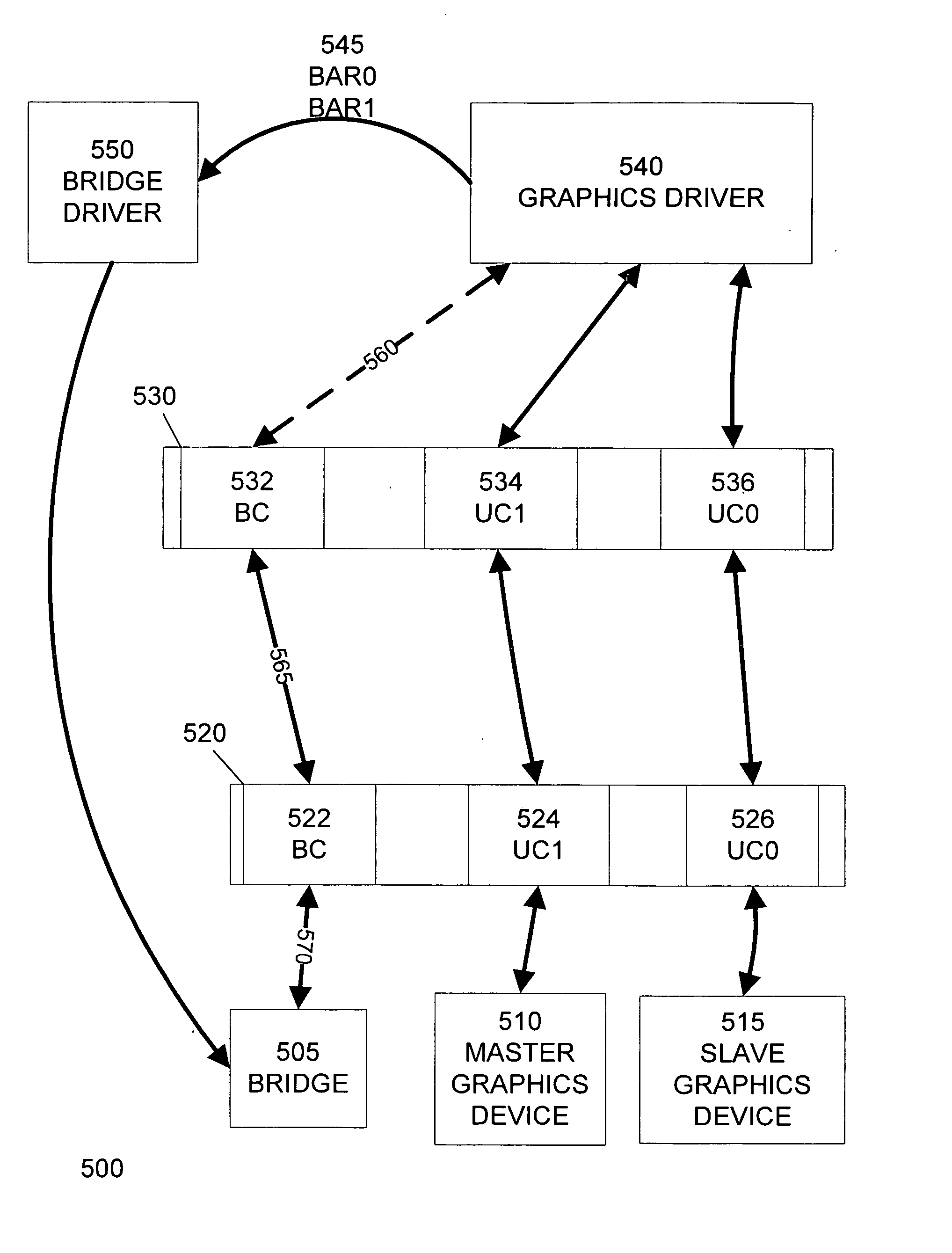
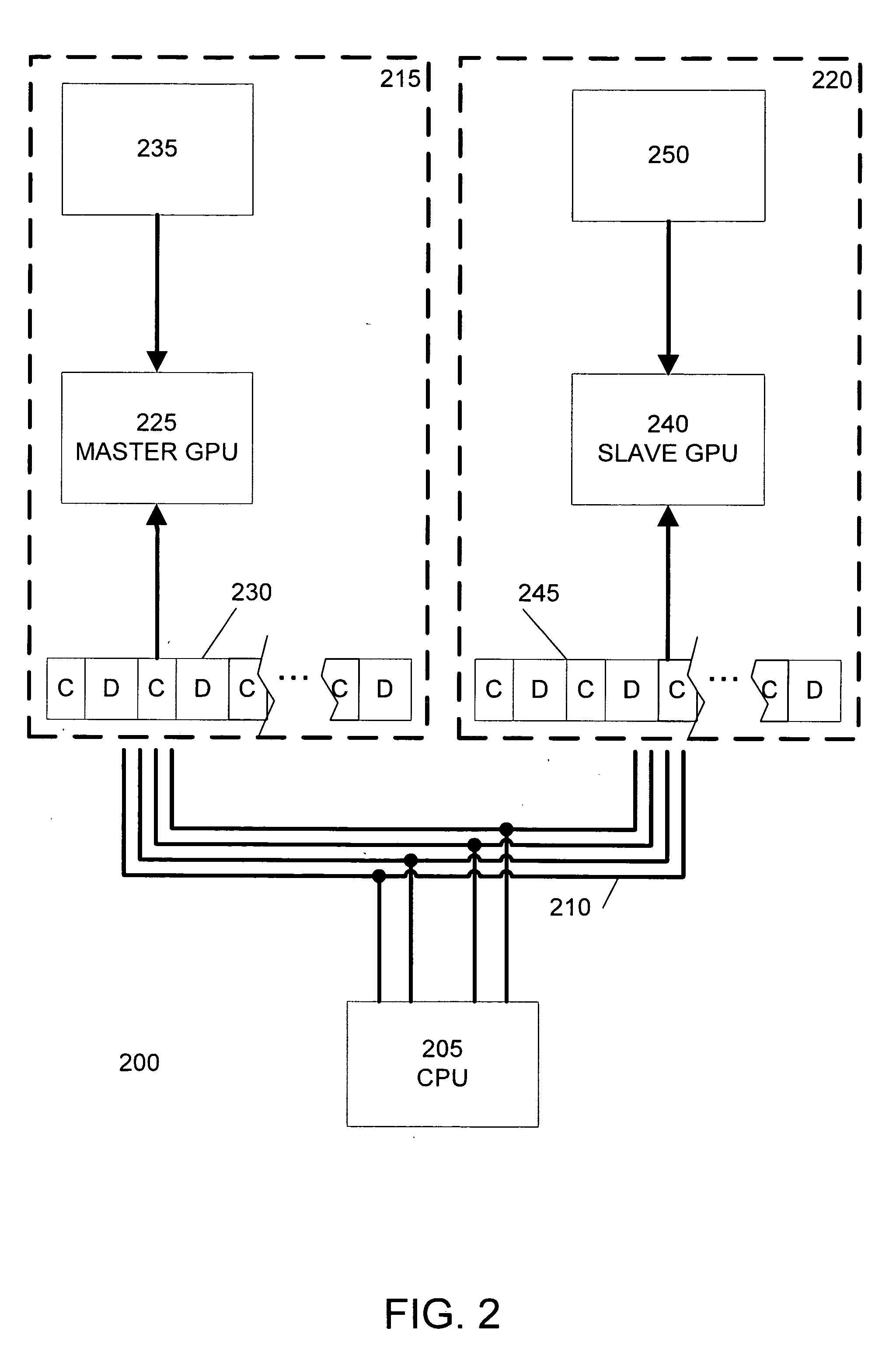
[0007] The invention includes a bridge associated with a broadcast aperture for facilitating the transfer of rendering commands and data between a processor and multiple graphics devices. The bridge receives data written by the processor to the broadcast aperture and forwards it to multiple graphics devices, eliminating the need for the processor to perform multiple write operations and possibly saturating the processor bus. During system initialization, a broadcast aperture is allocated to the bridge in address space based on an aperture size value set using a system configuration utility and stored in system configuration memory. A graphics driver activates the broadcast aperture by sending unicast aperture parameters associated with the multiple graphics devices to the bridge via a bridge driver. Upon activating the broadcast aperture, multiple graphics devices can be operated in parallel to improve rendering performance. Parallel rendering techniques include split-frame, alternate frame, and combined split- and alternate frame rendering.

Problems solved by technology

Transferring rendering commands and data with a CPU to two or more GPUs is one difficulty arising from parallel rendering schemes.
In these situations, the CPU bus is the limiting factor in overall graphics performance, and additional GPUs will not provide any performance improvement.
Furthermore, having the CPU communicate the same rendering commands and data with each GPU separately wastes CPU cycles; for example, requiring the CPU to write the same rendering commands and data several times.

Method used


Image

  • Graphics device clustering with PCI-express
  • Graphics device clustering with PCI-express
  • Graphics device clustering with PCI-express

Examples


Embodiment Construction

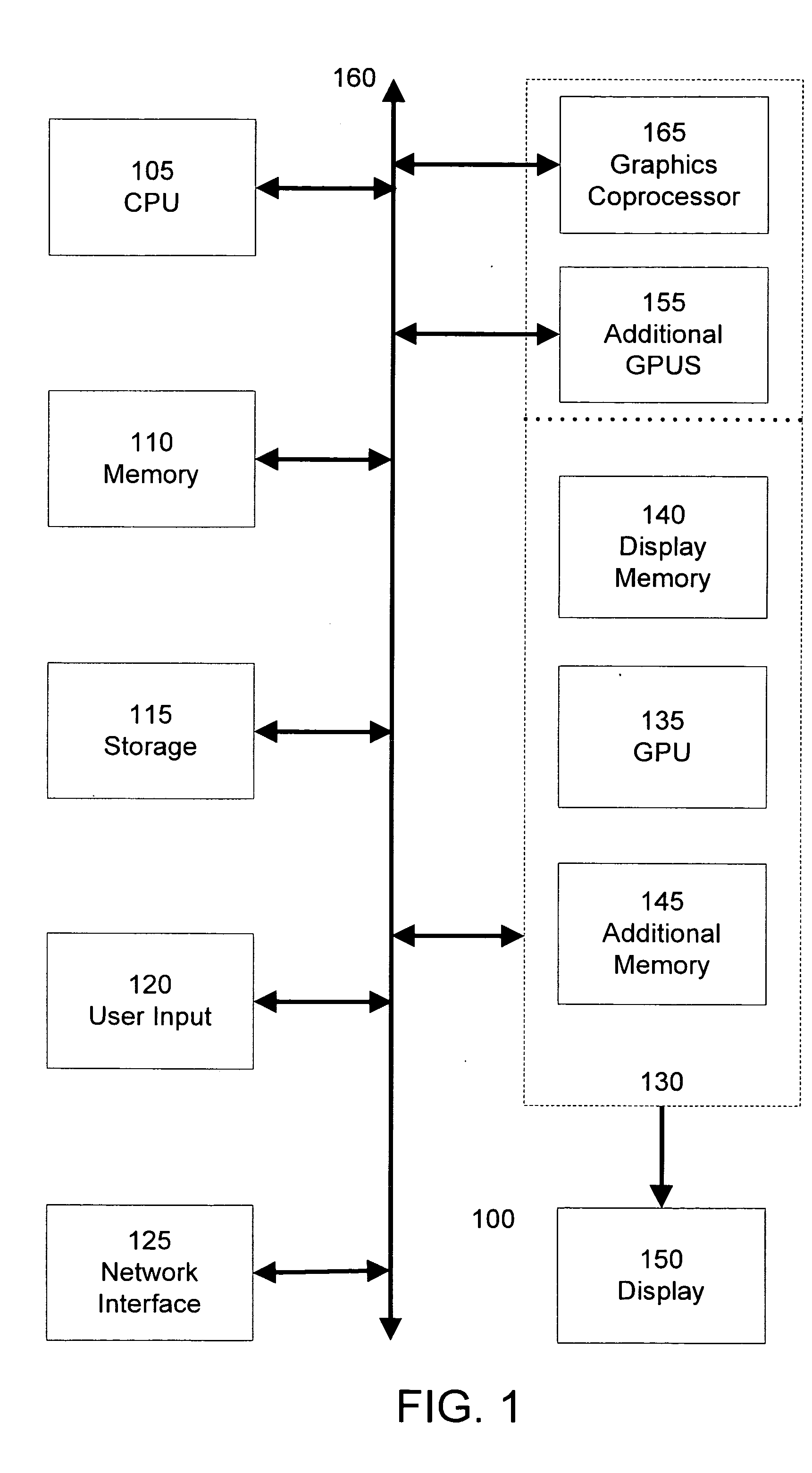
[0021]FIG. 1 is a block diagram of a computer system 100, such as a personal computer, video game console, personal digital assistant, or other digital device, suitable for practicing an embodiment of the invention. Computer system 100 includes a central processing unit (CPU) 105 for running software applications and optionally an operating system. In an embodiment, CPU 105 is actually several separate central processing units operating in parallel. Memory 110 stores applications and data for use by the CPU 105. Storage 115 provides non-volatile storage for applications and data and may include fixed disk drives, removable disk drives, flash memory devices, and CD-ROM, DVD-ROM, or other optical storage devices. User input devices 120 communicate user inputs from one or more users to the computer system 100 and may include keyboards, mice, joysticks, touch screens, and / or microphones. Network interface 125 allows computer system 100 to communicate with other computer systems via an e...


PUM


Abstract

A bridge associated with a broadcast aperture facilitates the transfer of rendering commands and data between a processor and multiple graphics devices. The bridge receives data written by the processor to the broadcast aperture and forwards it to multiple graphics devices, eliminating the need for the processor to perform duplicative(?) write operations. During system initialization, a broadcast aperture is allocated to the bridge in address space based on an aperture size value set using a system configuration utility and stored in system configuration memory. A graphics driver activates the broadcast aperture by sending unicast aperture parameters associated with the multiple graphics devices to the bridge via a bridge driver. Upon activating the broadcast aperture, multiple graphics devices can be operated in parallel to improve rendering performance. Parallel rendering techniques include split-frame, alternate frame, and combined split- and alternate frame rendering.

Description

CROSS-REFERENCES TO RELATED APPLICATIONS [0001] This application is related to the following patent applications, the disclosure of which are incorporated by reference herein for all purposes: “Adaptive Load Balancing in a Multi-Processor Graphics Processing System,” U.S. patent application Ser. No. 10 / 642,905, filed Aug. 18, 2003; “Programming Multiple Chips from a Command Buffer,” U.S. patent application Ser. No. 10 / 639,893, filed Aug. 12, 2003; and “Private Addressing in a Multi-Processor Graphics Processing System,” U.S. patent application Ser. No. 10 / 643,072, filed Aug. 18, 2003.BACKGROUND OF THE INVENTION [0002] The present invention relates to the field of computer graphics. Many computer graphic images are created by mathematically modeling the interaction of light with a three dimensional scene from a given viewpoint. This process, called rendering, generates a two-dimensional image of the scene from the given viewpoint, and is analogous to taking a photograph of a real-wor...

Claims


Application Information

Patent Timeline
IPC IPC(8): G06F3/14G06F15/16G06T1/20G06T15/00G09G5/36
CPCG06F3/14G06F3/1438G09G5/363G06T15/005G06T1/20
Inventor DIARD, FRANCK R.REED, DAVID G.HICOK, GARY D.COX, MICHAEL BRIAN
Owner NVIDIA CORP
Learn More