
Structure for supplying hot air for drying clothes in drum type washing machine and operation control method thereof

Inactive Publication Date: 2005-09-01
LG ELECTRONICS INC
View PDF5 Cites 24 Cited by
  • Summary
  • Abstract
  • Description
  • Claims
  • Application Information

AI Technical Summary

Benefits of technology

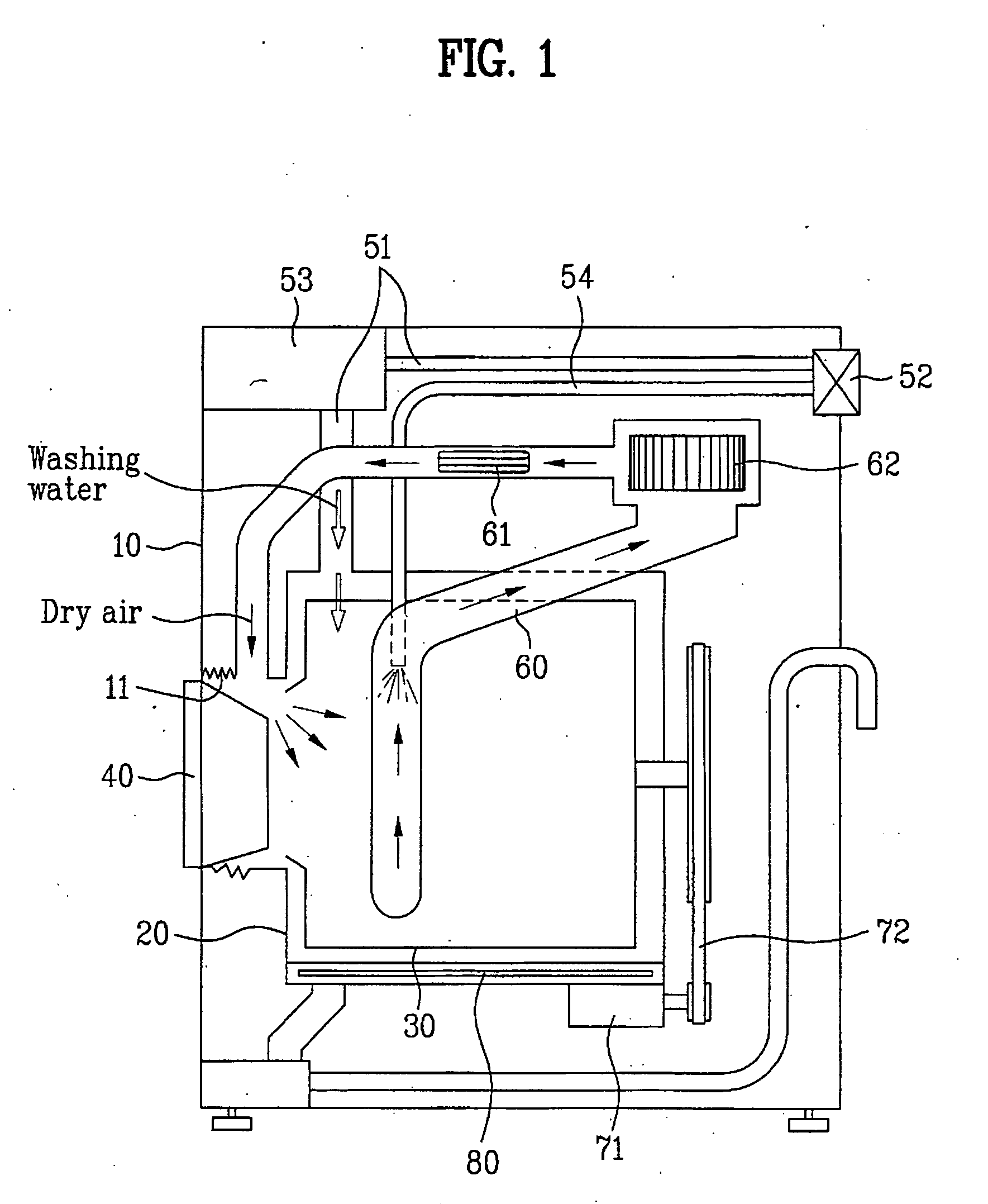
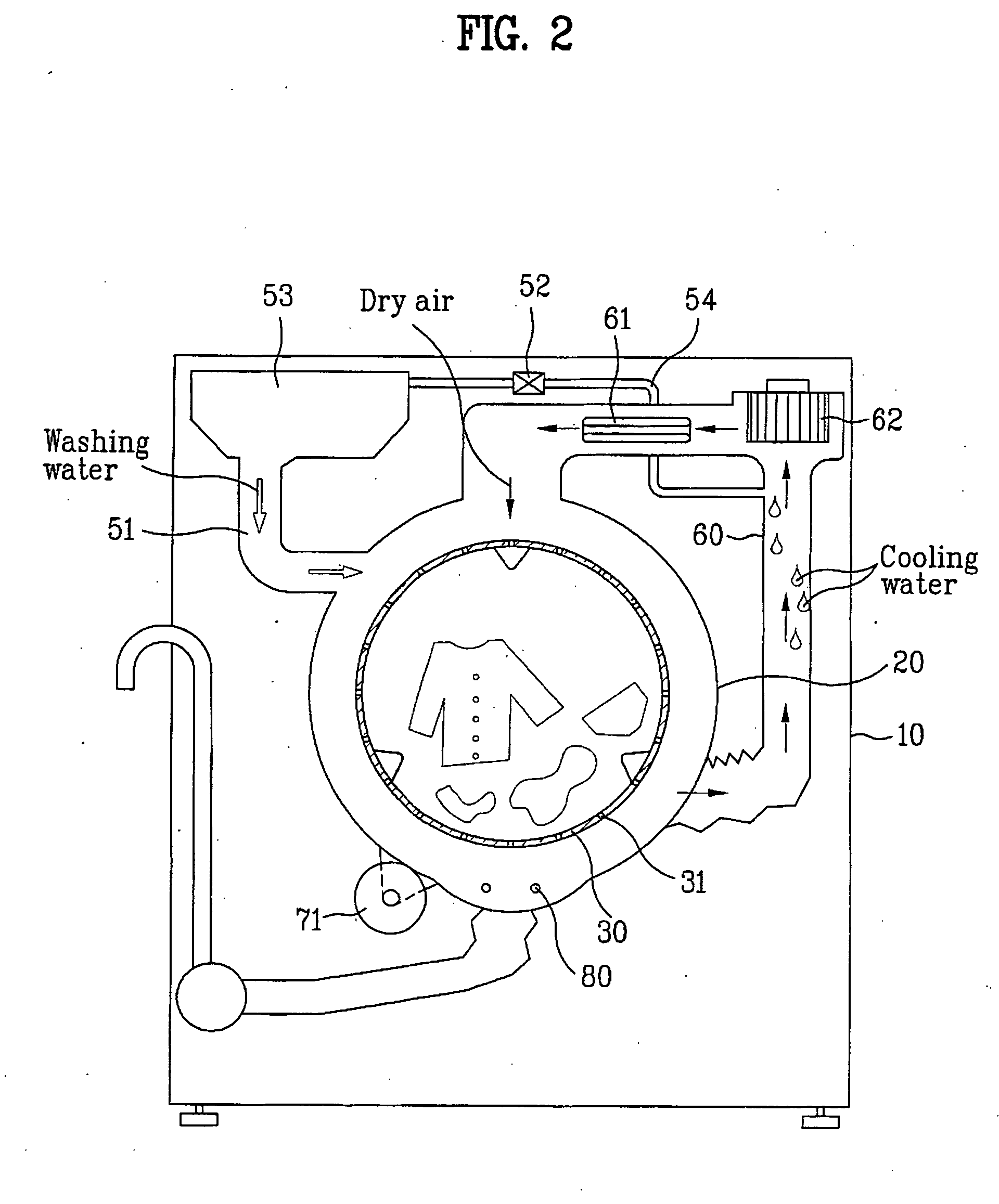
[0025] An object of the present invention is to provide a structure for supplying hot air in a drum washing machine and an operation control method thereof, in which hot air can be blown deep into an inside of the drum, to introduce the hot air into an inside space of the drum uniformly for drying the laundry. That is, the object of the present invention is to provide a structure for supplying hot air and an operation control method thereof, which enables full use of the hot air introduced into the inside of the drum for enhancing the drying performance, and efficiency.
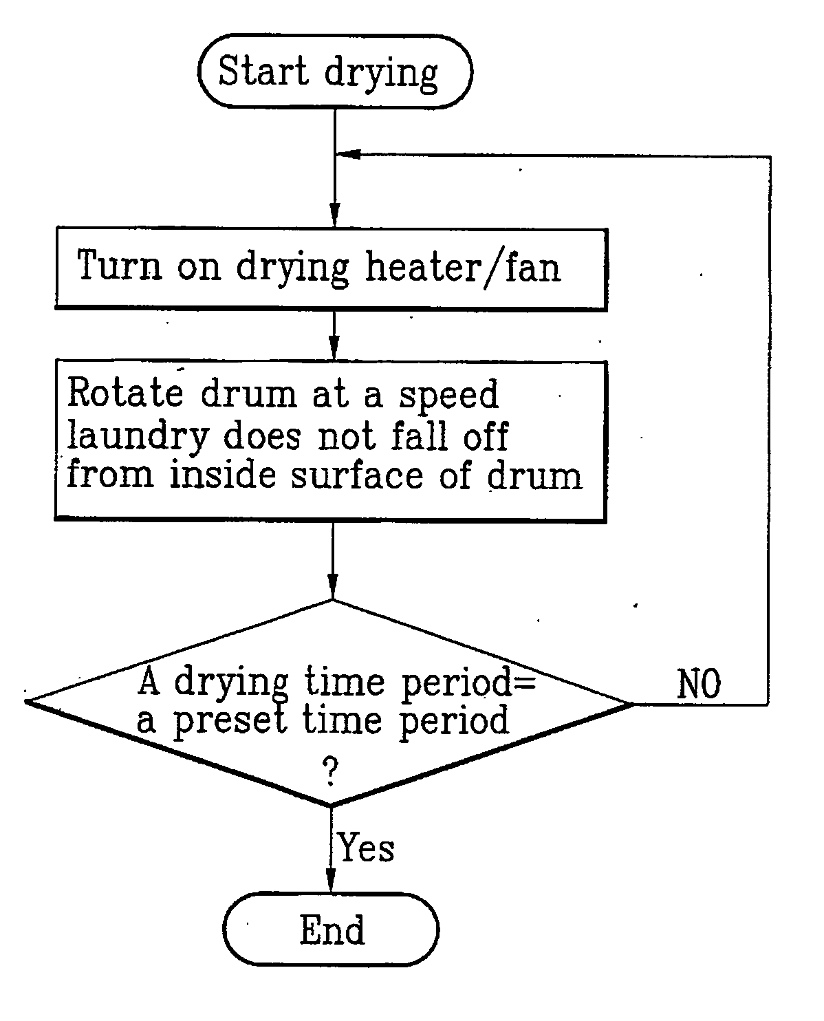
[0029] In another aspect of the present invention, a method for controlling operation of a horizontal or tilt type drum washing machine including a tub for holding washing water, a drum rotatably mounted in the tub, for introducing laundry therein, a drum driving motor for providing driving force to rotate the drum, a drying heater for heating air being supplied to an inside of the drum, a drying duct forming a flow passage for supplying hot air heated by the drying heater to the inside of the drum, and a fan for forced supply of the hot air heated by the drying heater to the inside of the drum, the method including the step of supplying the hot air to an inside of the drum while rotating the drum at a speed equal to, or higher than a speed enough to keep the laundry in the drum to be attached to, and not to fall off from, an inside surface of the drum in progressing of a drying cycle.

Problems solved by technology

Therefore, since the hot air escapes the drum 30 before the hot air can be used fully for drying in the drum 30, the drying performance, and efficiency are impaired, and input of unnecessary energy is required, resulting in waste of energy.
In short, with regard to a main flow path of the hot air in the related art drum washing machine, because the hot air fails to reach to the laundry located far from a hot air inlet fully, failing to dry the laundry uniformly to impair the drying performance, to require drying for a long time, the drying efficiency is also dropped.

Method used


Image

  • Structure for supplying hot air for drying clothes in drum type washing machine and operation control method thereof
  • Structure for supplying hot air for drying clothes in drum type washing machine and operation control method thereof
  • Structure for supplying hot air for drying clothes in drum type washing machine and operation control method thereof

Examples


first embodiment

[0078] The hot air flows along a direction of a drum driving shaft line in the drum, for which it is preferable that the hot air is supplied from a front to a rear of the drum, or vice versa, like the

[0079] Alike the first embodiment, the dry progressing step may include a section in which the rotation speed of the drum is maintained at a speed equal to, or higher than a speed (for an example, 100 rpm) enough to keep the laundry in the drum to be attached to, and not to fall off from, but not to be attached closely to, the inside circumferential surface of the drum, and a section in which the rotation speed of the drum is reduced to a low speed (about 20˜30 rpm) at which the laundry in the drum is unable to be attached to the inside circumferential surface of the drum.

[0080] Thus, the embodiment enables to reduce a drying time period as the drying heater and the fan are turned on starting from the inertial rotation of the drum following finishing of spinning to supply hot air, and ...

second embodiment

[0082] If the drum washing machine of the first or second embodiment is further provided with means in the drum 30 for determining dryness (for an example, an electrode sensor: not shown) of the laundry, the following operation control method is also viable.

[0083] That is, a method for controlling operation of a horizontal or tilt drum washing machine in accordance with a third preferred embodiment of the present invention includes the steps of measuring dryness of laundry in the drum in a state the drum is stationary after finish of spinning, supplying hot air to an inside of the drum while rotating the drum at a speed equal to or higher than a speed at which an outward acceleration acting on a point of an inside circumferential surface of the drum in a radial direction of the drum is equal to an acceleration of the gravity if the dryness measured in above step is below a preset dryness, and supplying hot air to an inside of the drum while rotating the drum at a reduced speed at wh...

fourth embodiment

[0098] The finish of drying may be simply set to finish the drying at the time the set time is reached. Or alternatively, the drying may be finished by setting a drying time period, measuring the dryness when the set drying time period is reached, and extending the drying time period according to the measured dryness. Or alternatively, regardless of a set drying time period, the finish of drying may be determined with reference to a preset dryness which is different from the set dryness in the third or

[0099]FIG. 11 illustrates a graph showing a rotation speed of a motor for driving the drum, and turn on / off states of drying heater and fan while drying.

[0100] Referring to FIG. 8, it can be known that a section for progressing drying at a speed in which the laundry can not be attached to, but fall off from the inside surface of the drum in a state the drying heater and the fan are turned on, a section in which the drum driving motor is turned on to accelerate the drum to a speed high...


PUM


Abstract

Structure for supplying hot air to a drum washing machine, and operation control method thereof, in which uniform introduction of hot air deep into an inside of a drum is made possible for enhancing drying capability and efficiency. For this, a drum washing machine includes a tub for holding washing water, a drum rotatably mounted in the tub, for introducing laundry therein, a drying heater for heating air being supplied to an inside of the drum, a drying duct forming a flow passage for supplying hot air heated by the drying heater to the inside of the drum, a fan for forced supply of the hot air heated by the drying heater to the inside of the drum, a hot air inlet at a front side of the drum for supplying the hot air to the inside of the drum, and a humid air recovery opening at a rear side of the drum for recovering humid air from the inside of the drum, and the operation control method of a drum washing machine includes the step of supplying hot air to an inside of the drum while rotating the drum at a speed equal to, or higher than a speed enough to keep the laundry in the drum attached to, and not fall off from, the inside surface of the drum in progressing a drying cycle.

Description

CROSS-REFERENCE TO RELATED APPLICATIONS [0001] This application claims the benefit of Korean Application Nos. P2004-0010412 and P2004-0010413, both filed on Feb. 17, 2004, which are hereby incorporated by reference as if fully set forth herein. BACKGROUND OF THE INVENTION [0002] 1. Field of the Invention [0003] The present invention relates to drum type washing machines, and more particularly, to a structure for supplying hot air, in which uniform introduction of hot air deep into an inside of a drum is made possible for enhancing drying capability and efficiency; and an operation control method thereof. [0004] 2. Discussion of the Related Art [0005] In general, in the washing machines, there are a pulsator type washing machine of a top loading type, and a drum type washing machine (in general called as a drum washing machine) having a drum laid down in a horizontal direction, substantially. [0006] As described before, since the drum is laid down in a horizontal direction, the drum ...

Claims


Application Information

Patent Timeline
IPC IPC(8): D06F25/00D06F58/24D06F58/28
CPCD06F25/00D06F2058/2838D06F58/28D06F58/38D06F2103/08D06F2103/10D06F2105/46D06F2105/48
Inventor AHN, BYUNG HWANKIM, KWANG SOO
Owner LG ELECTRONICS INC
Learn More