
Audio signal processing system

a signal processing and audio technology, applied in the field of audio signal processing system, can solve the problems of poor operability, difficult operation of monitoring signals at a plurality of positions in sequence, and usable output nodes, and achieve the effect of easy monitoring of signals during processing

Inactive Publication Date: 2005-08-18
YAMAHA CORP
View PDF4 Cites 9 Cited by
  • Summary
  • Abstract
  • Description
  • Claims
  • Application Information

AI Technical Summary

Benefits of technology

[0010] An object of the invention is to solve the above-described problems and to make it possible to easily monitor a signal during processing in an audio signal processing system including an audio signal processing device having a signal processor wherein processing contents can be programmed and an editing device for editing the configuration of signal processing in the audio signal processing device.

Problems solved by technology

Accordingly, when the monitoring is performed, there is a problem of usable output nodes, for outputting signal after processing, being fewer than those originally usable.
In addition, when a signal at another position is to be monitored, there is another problem of the necessity to reedit the signal processing configuration and set it again in the audio signal processing device, resulting in poor operability.
In particular, an operation of monitoring signals at a plurality of positions in sequence is difficult to perform.
The signal processing relating to the wire for monitoring is performed as a series of signal processing similar to signal processing of other portions, and therefore the edited signal processing configuration using hardware resource of the audio signal processing device to the fullest extent, may bring about another problem of failing to add the wire for monitoring.

Method used


Image

  • Audio signal processing system
  • Audio signal processing system
  • Audio signal processing system

Examples


Embodiment Construction

[0027] Hereinafter, a preferred embodiment of the invention will be concretely described with reference to the drawings.

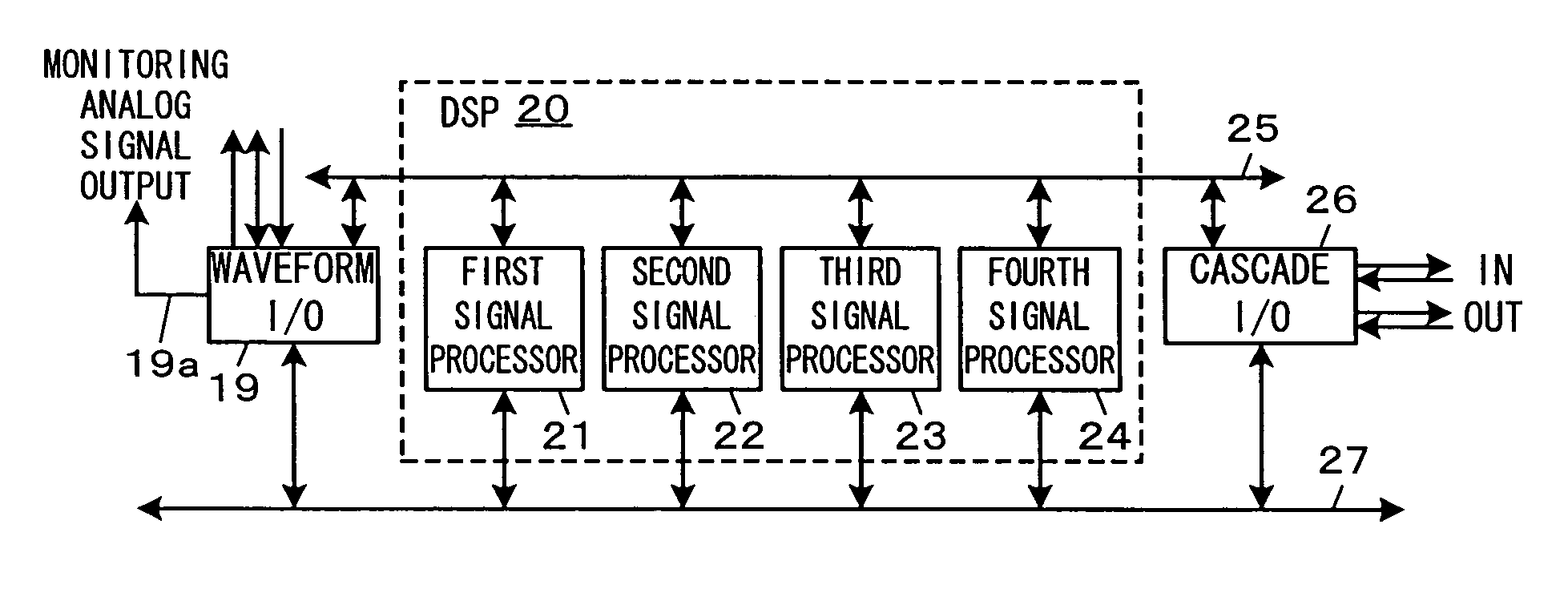
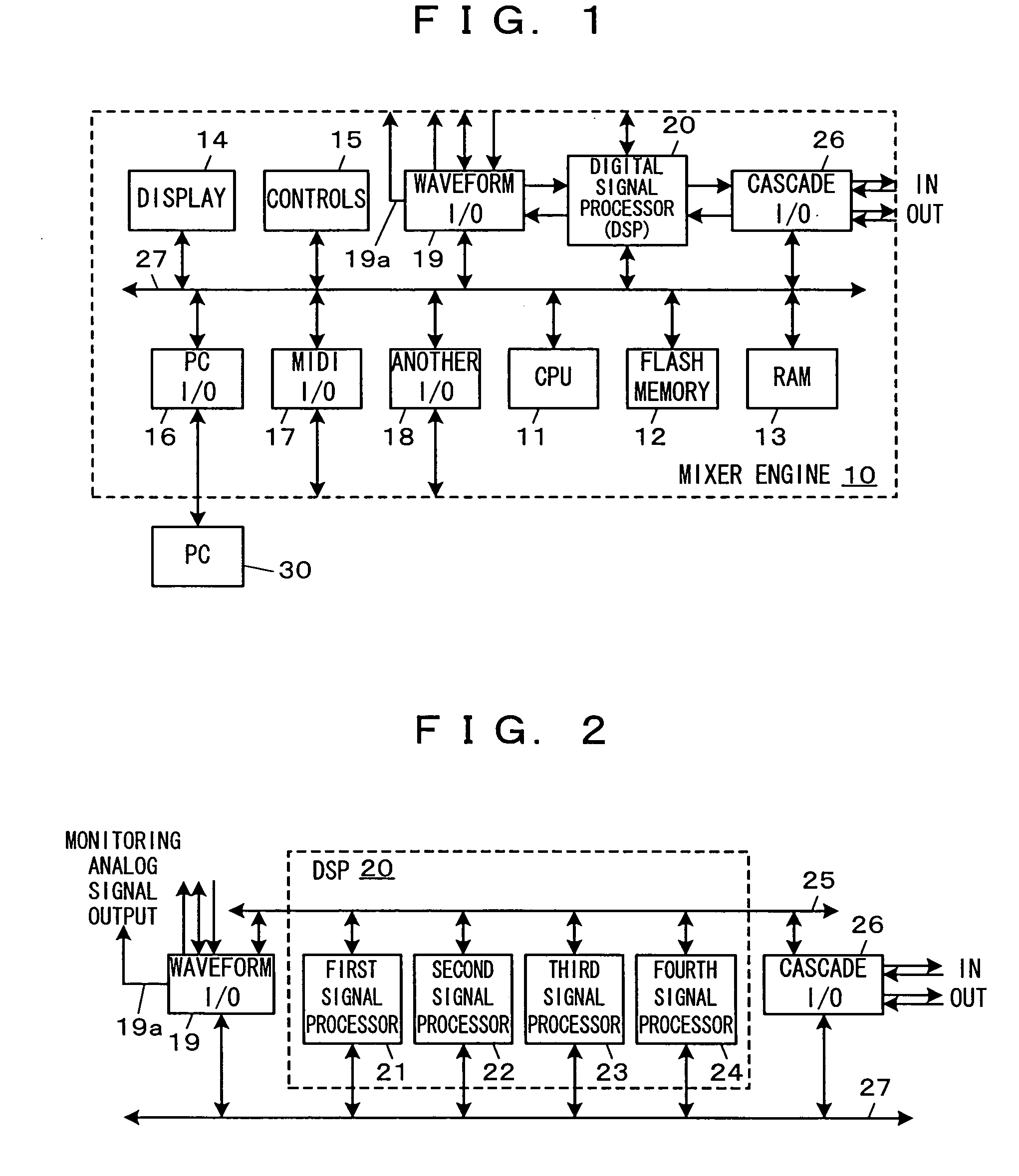
[0028] A configuration of a mixer system being an embodiment of an audio signal processing system of the invention which comprises a PC being an editing device and a mixer engine being an audio signal processing device will first be described using FIG. 1. FIG. 1 is a block diagram showing the configuration of the mixer system.

[0029] As shown in FIG. 1, the mixer system comprises a mixer engine 10 and a PC 30. The PC 30 can employ, as hardware, a well-known PC having a CPU, a ROM, a RAM and so on and a display, that is, a PC on which an operating system (OS) such as Windows XP (registered trademark) runs. By executing an edit program being an embodiment of a program of the invention as an application program on the OS, the PC 30 can function as the editing device which edits a configuration of signal processing in the mixer engine 10, transfers the edit result to...


PUM


Abstract

In a mixer system including a mixer engine wherein contents of signal processing can be programmed and a PC that edits the configuration of signal processing, the PC is provided with a display controller that graphically displays the edited configuration of signal processing using components for the signal processing and wires connecting nodes of the components; an accepting device that accepts designation of a node or wire whose signal is desired to be monitored, in a screen thereof; and a directing device that directs the mixer engine to output the signal from the designated node or wire to a monitoring analog signal output in accordance with the designation, and the mixer engine is provided with an outputting device that outputs a signal to the monitoring analog signal output in accordance with the direction separately from the signal processing relating to the edited signal processing configuration.

Description

BACKGROUND OF THE INVENTION [0001] 1. Field of the Invention [0002] The invention relates to an audio signal processing system in which an editing device edits contents of signal processing in an audio signal processing device and the audio signal processing device performs the signal processing in accordance with the edited contents, and a program for causing a computer to function as the editing device. [0003] 2. Description of the Related Art [0004] Conventionally, there has been a well-known audio signal processing device in which an audio signal processing module is composed using a processor operable following a program, and an external computer such as a PC (personal computer) or the like functions as an editing device so that audio signals can be processed based on a configuration of signal processing edited using the editing device. Such an audio signal processing device is called a mixer engine in the present application. The mixer engine stores therein the configuration o...

Claims


Application Information

Patent Timeline
IPC IPC(8): G09G1/06G10L11/00H04N9/64
CPCH04H60/04G10H2220/106
Inventor TAKEMURA, SATOSHIMIWA, AKIHIROHIROI, MAKOTO
Owner YAMAHA CORP
Learn More