
Pump unit

a pump unit and pump technology, applied in the field of pump units, can solve the problems of increased cost, increased discharge pressure, excessive noise and vibration of the pump unit, etc., and achieve the effects of reducing noise and vibration, high discharge pressure, and high flow rate operations

Active Publication Date: 2005-08-18
DAIKIN IND LTD
View PDF19 Cites 12 Cited by
  • Summary
  • Abstract
  • Description
  • Claims
  • Application Information

AI Technical Summary

Benefits of technology

The present invention provides a pump unit that can achieve a high discharge pressure with a small-torque motor, while reducing noise and vibrations during high flow-rate operations. The pump unit includes a first fixed-capacity type pump and a second fixed-capacity type pump, a discharge line connected to both pumps, a variable-speed motor for driving the pumps, a switching valve for connecting or disconnecting the discharge lines, a pressure sensor for detecting pressure, and a control device for controlling the switching valve based on the pressure sensor and the motor's speed. The control device autonomously controls the discharge pressure and flow rate, eliminating the need for external command signals. The pump unit provides high discharge pressure with a small-sized motor, reducing the size of the pump. The switching valve is switched based on the motor's speed and the detected pressure, preventing instability of the valve and simplifying the wiring.

Problems solved by technology

Using the large-torque motor would cause a problem of an upsizing of the pump unit as well as an increase in cost.
Also, using the small- and fixed-capacity type pump would cause the rotational speeds of the pump and the motor to become excessively large ones during high flow-rate operations, posing a problem of excessively large noise and vibrations of the pump unit.

Method used


Image

  • Pump unit
  • Pump unit
  • Pump unit

Examples


Embodiment Construction

[0031] Hereinbelow, the present invention is described in detail by embodiments thereof illustrated in the accompanying drawings.

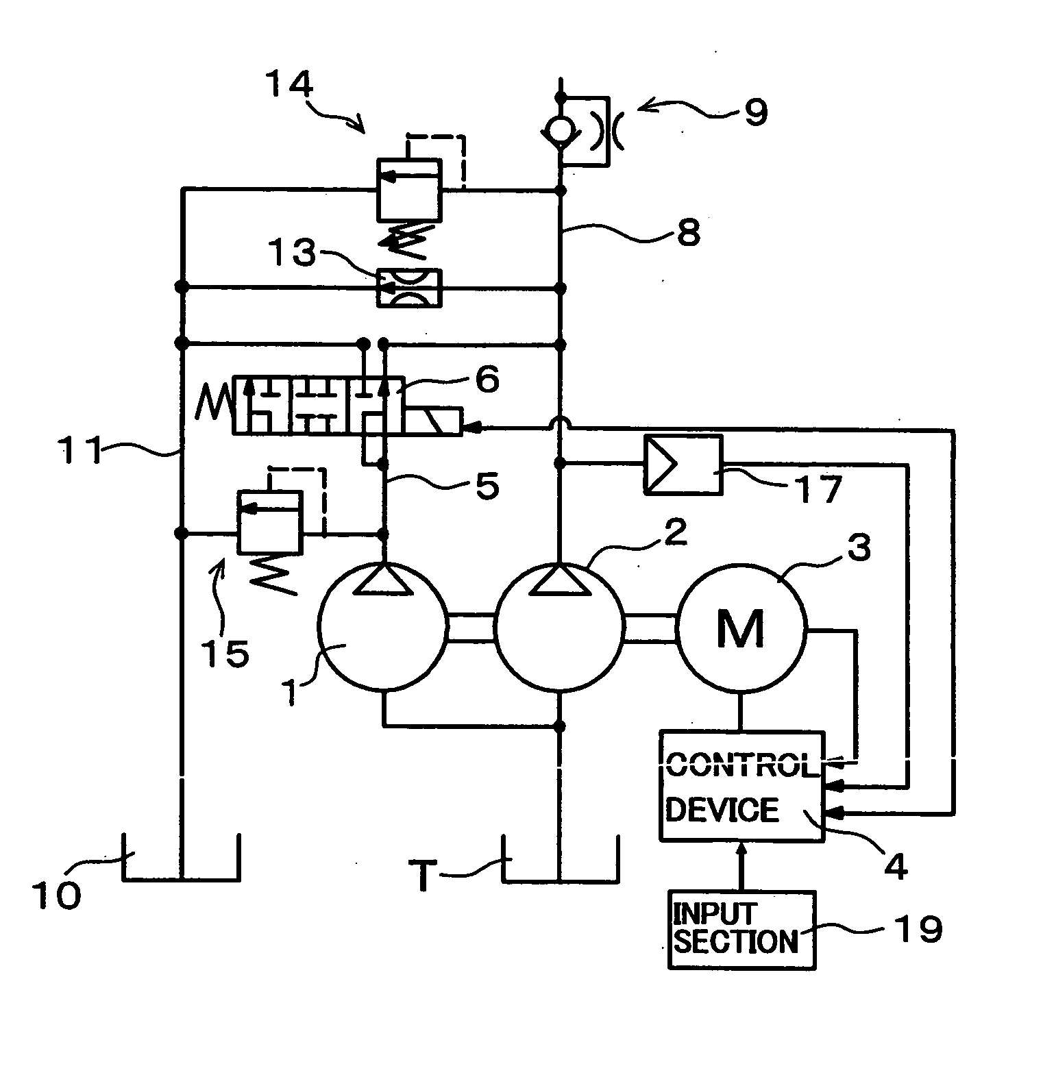
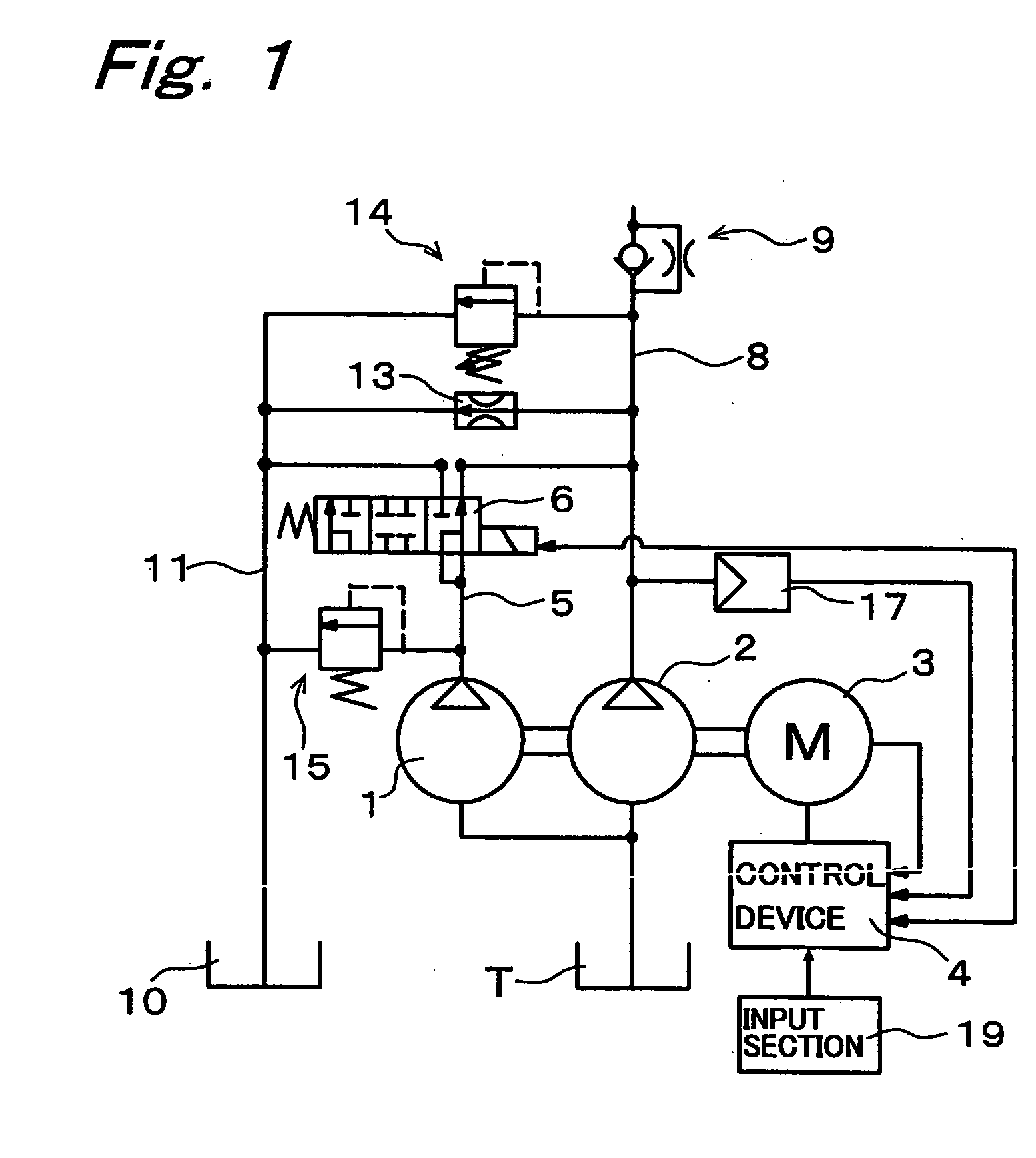
[0032]FIG. 1 is a view showing a pump unit of an embodiment of the present invention. This pump unit is a pump unit that feeds a working fluid of a tank T to an unshown actuator such as hydraulic cylinder. This pump unit has a first pump 1 as a first fixed-capacity type pump of large capacity, and a second pump 2 as a second fixed-capacity type pump of small capacity directly connected to the first pump 1. The first pump 1 is a gear pump of 5.5 cc / rev., and the second pump 2 is a gear pump of 3.5 cc / rev. These first pump 1 and second pump 2 are connected to a variable-speed motor 3, and this variable-speed motor 3 is electrically connected to a control device 4. An outlet port of the first pump 1 is connected to a first discharge line 5, and an outlet port of the second pump 2 is connected to a second discharge line 8. The first discharge line 5 is connec...


PUM


Abstract

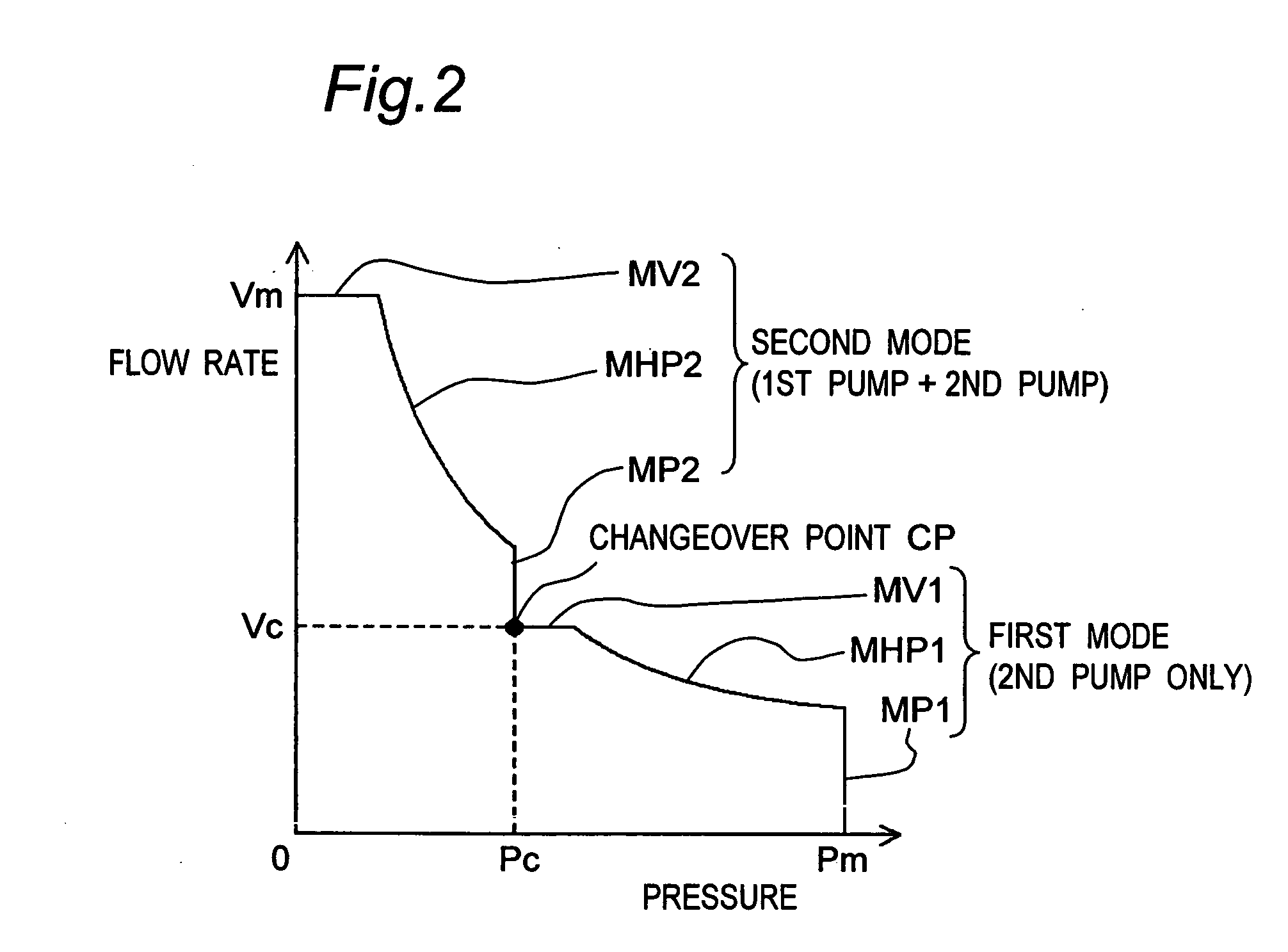
A first pump of small capacity and a second pump of large capacity are connected directly with each other and are driven by a variable-speed motor. The rotational speed of the variable-speed motor is controlled by a control device. In a first mode, a first discharge line of the first pump and a second discharge line of the second pump are disconnected with each other, making the first pump unloaded. With the first pump in the unloaded, state, a constant-horsepower operation is performed, where the discharge fluid is brought into a high pressure by relatively small torque. In a second mode, the first discharge line and the second discharge line are connected with each other by a switching valve. With the first and second discharge lines in the connected, state, a constant-horsepower operation is performed, where a high flow rate of discharge fluid is discharged at relatively low rotational speed.

Description

TECHNICAL FIELD [0001] The present invention relates to a pump unit. BACKGROUND ART [0002] Conventionally, there has been provided a pump unit shown in FIG. 4. This pump unit has a fixed-capacity type pump 52 whose rotational speed is variably driven by a variable-speed motor 51, and a controller 53 for controlling the rotational speed of the variable-speed motor 51 by changing the frequency of supply current to the motor 51. This controller 53, upon receiving a signal from a pressure sensor 54 which detects a pressure of a discharge line of the pump 52, controls the rotational speed of the variable-speed motor 51 so that the value of the pressure detected by the pressure sensor 54 becomes a specified value, thus controlling the rotational speed of the pump 52. [0003] However, in this conventional pump unit, since one fixed-capacity type pump 52 is driven by the variable-speed motor 51, a large-torque motor or a small- and fixed-capacity type pump needs to be used in order to obtain...

Claims


Application Information

Patent Timeline
Patent Type & Authority Applications(United States)
IPC IPC(8): F04B49/00F04B49/06F04B49/08F04C14/02F04C14/06F04C14/08
CPCF04B49/002F04B49/007F04B49/06F04B49/065F04C2270/56F04C14/02F04C14/06F04C14/08F04B49/08
Inventor HORIUCHI, HITOSHIOCHI, YOSHIYUKINAKATSUJI, JUN
Owner DAIKIN IND LTD
Learn More