
Apparatus and methods for treating tooth root canals

Active Publication Date: 2005-08-04
INTERMED
View PDF1 Cites 83 Cited by
  • Summary
  • Abstract
  • Description
  • Claims
  • Application Information

AI Technical Summary

Benefits of technology

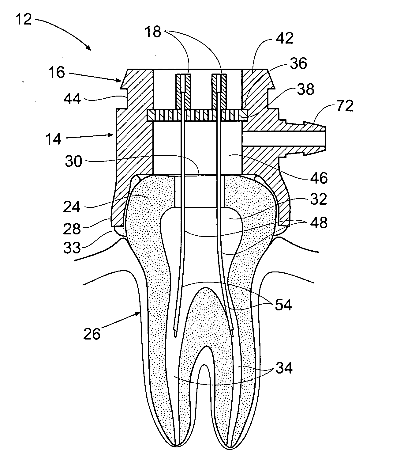
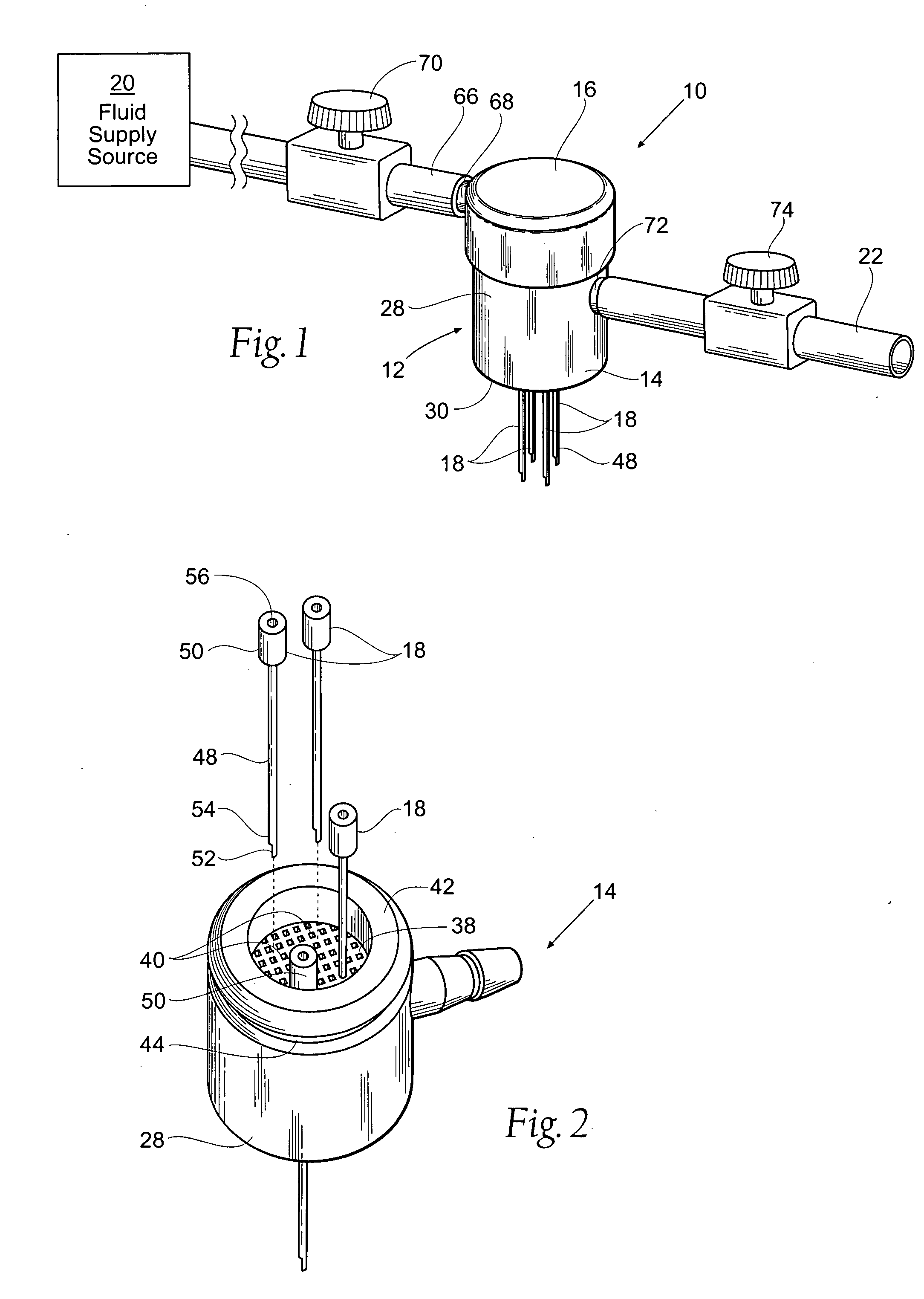
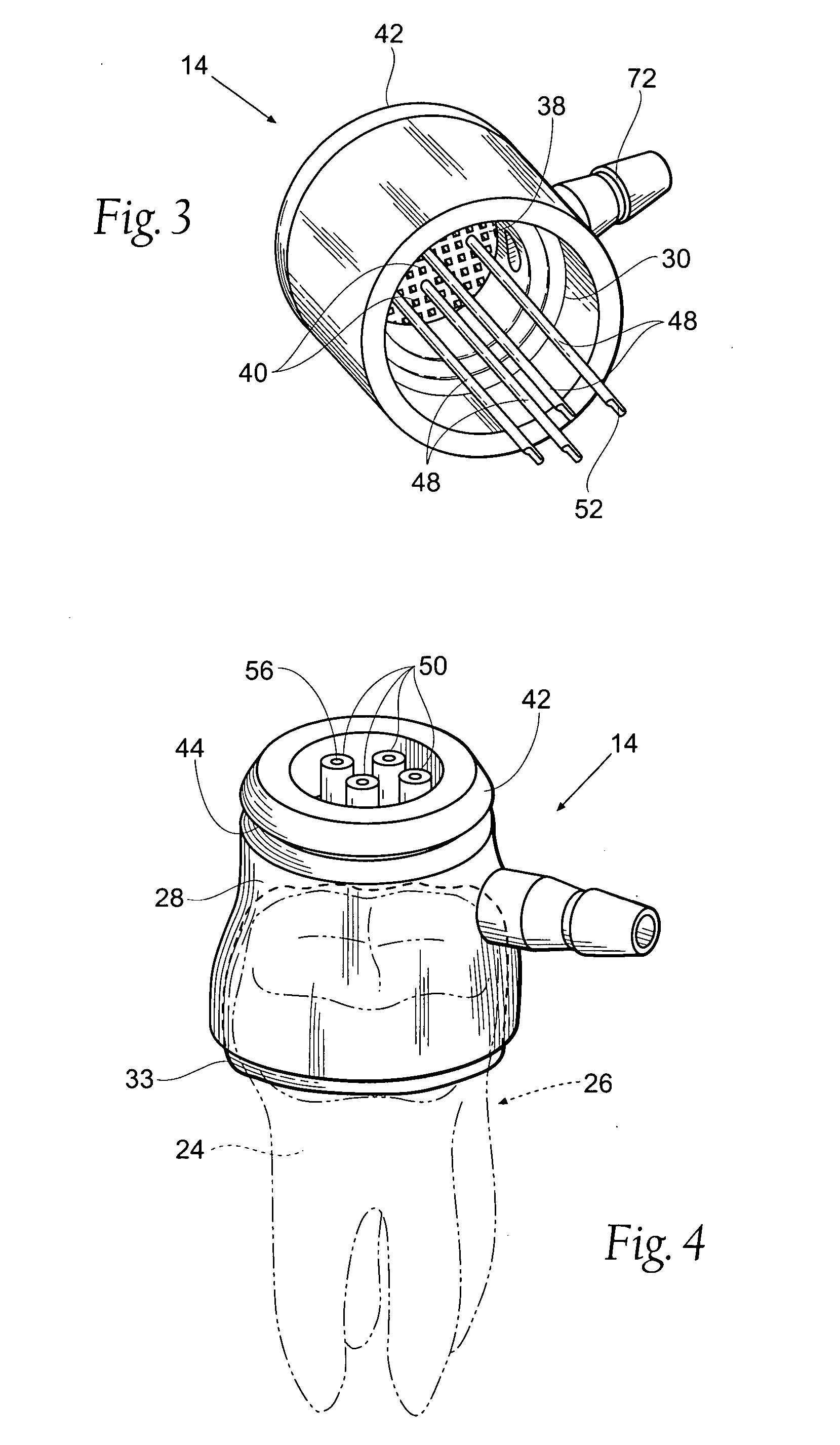
[0012] According to one aspect of the invention, a tooth root canal treatment system comprises a manifold having a base member sized and configured to rest on a crown of a tooth and a top member sized and configured to couple with the base member. The base and top members together define an inlet chamber and an outlet chamber. A fluid supply source is coupled to the inlet chamber. A draining mechanism is coupled to the outlet chamber. Means are provided for preventing fluid communication between the inlet chamber and the outlet chamber.

Problems solved by technology

The pulp canals present the most difficult portion of the tooth to be cleaned.
A tooth can be mono- or pluri-rooted, increasing the complexity of the tooth treatment.
Inherent with the positioning of teeth inside a patients mouth, space is limited to perform this intricate work.
This requires the instruments to be small and delicate, presenting the problem of the instruments breaking within the pulp canal, which may necessitate complete removal of the tooth.
In some cases the pulp canal is so fine that mechanical treatment is precluded.
The cleaning reduces bacteria and other debris that could result in infection or abscess or otherwise result in a less than satisfactory outcome.
Manual treatment and irrigation of the dental root is a tedious and time-consuming task.
In addition, manual methods may not consistently fill and drain the entire pulp chamber and pulp canals, resulting in less than satisfactory preparation of the tooth.
One inherent problem with such systems is delivering the solution to the bottom of the fluid reservoir with sufficient pressure to consistently dislodge debris deep within the pulp canal.

Method used


Image

  • Apparatus and methods for treating tooth root canals
  • Apparatus and methods for treating tooth root canals
  • Apparatus and methods for treating tooth root canals

Examples


Embodiment Construction

[0038] Although the disclosure hereof is detailed and exact to enable those skilled in the art to practice the invention, the physical embodiments herein disclosed merely exemplify the invention that may be embodied in other specific structure. While the preferred embodiment has been described, the details may be changed without departing from the invention, which is defined by the claims.

I. Tooth Manifold

[0039]FIG. 1 shows a system 10 for delivery and evacuation of a material to a pulp chamber and pulp canals deep within a tooth root during endodontic or root canal therapy. The system 10 includes a tooth manifold 12 having a bottom or base member 14 and a cap 16. The manifold 12 supports an irrigation needle 18 that permits fluid flow through the manifold 12, as will be described in detail later. The manifold 12 is coupleable to a fluid supply source 20 and evacuation tubing 22 to control and regulate delivery of fluid and evacuation of spent fluid, as will also be described in g...


PUM


Abstract

Systems and methods provide for automated, cyclic delivery and evacuation of a treatment or irrigation solution from a tooth root pulp chamber and pulp canals. A manifold has a base member sized and configured to rest on a crown of an instrumented tooth and a top member sized and configured to couple with the base member to define an inlet chamber and an outlet chamber. The distal end of a needle is passed through an opening between the inlet and outlet chambers and extended distally beyond the base member into a pulp canal. The proximal end of the needle includes an opening in fluid communication with the inlet chamber. A solution is transferred from a fluid supply source to the inlet chamber and through the needle into the pulp chamber and pulp canals. The spent solution is evacuated from the pulp chamber and pulp canals through the outlet chamber.

Description

FIELD OF THE INVENTION [0001] The invention relates to devices and methods for the treatment and irrigation of dental pulp chambers and pulp canals. BACKGROUND OF THE INVENTION [0002] Endodontic or root canal therapy is a common procedure in which a dentist or endodontist removes the nerve and dental pulp from a tooth in cases where the nerve has been damaged by a cavity, trauma (e.g., fracture of the tooth), disease (e.g., infection), or other reasons. This procedure not only allows the individual to keep a tooth that otherwise could have had to be removed, but relieves the individual of pain and discomfort. [0003] The treatment typically requires the removal of the pulp tissue from the canal(s). The pulp chamber and root canal(s) of the tooth are then cleaned. Finally, the pulp chamber is shaped and sealed. [0004] The tooth to be treated is either living, and its canals contain a vasculo-nervous bundle, or is dead and its canals then contain a necrotic magma. The pulp canals prese...

Claims


Application Information

Patent Timeline
IPC IPC(8): A61C5/04
CPCA61C5/04A61C5/02A61C5/40A61C5/50
Inventor POND, GARY J.
Owner INTERMED
Learn More